Battery charging and discharging parameter identification method and system for electric vehicle
A technology for charging and discharging parameters and electric vehicles. It is applied in the direction of measuring electricity, measuring electrical variables, and measuring devices. It can solve the problems of low implementability and poor operability, so as to save energy, improve utilization, and avoid large currents. impact effect
- Summary
- Abstract
- Description
- Claims
- Application Information
AI Technical Summary
Problems solved by technology
Method used
Image
Examples
Embodiment 1
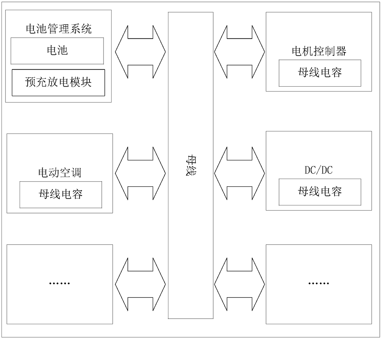
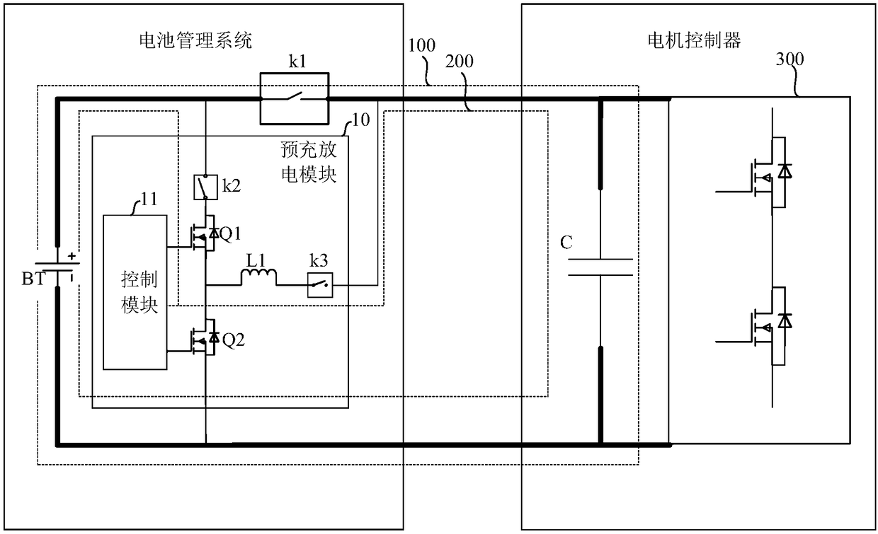
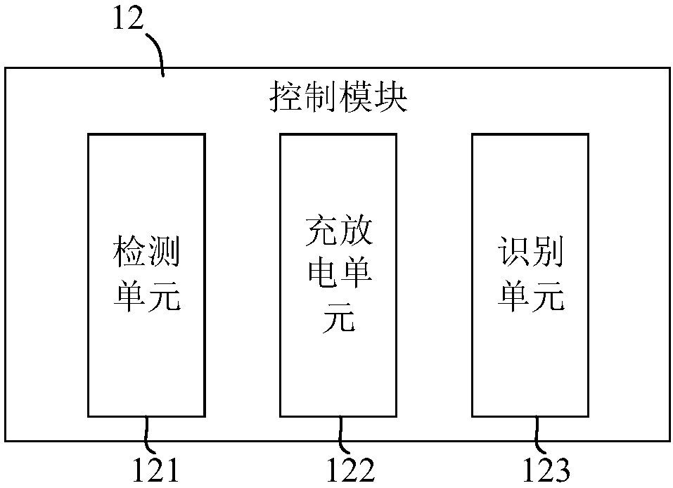
[0031] See Figure 1-3 The connection of the battery charging and discharging parameter identification system of the electric vehicle in the embodiment of the present invention with the battery BT and the bus capacitor C is based on a battery management system (Battery Management System, BMS). The battery management system may be vehicle-mounted, which includes the battery status Basic functions such as detection (current, voltage, temperature), battery status analysis, battery safety protection, energy control management, and battery information management.
[0032] To facilitate the description of the embodiments of the present invention, such as figure 2 As shown, this embodiment takes the bus capacitor C of the motor controller as an example, and during the application of the battery charge and discharge parameter identification system, it is actually connected to the bus capacitors of each on-board equipment, that is, the bus capacitor C is the motor controller, electric The...
Embodiment 2
[0045] See Figure 4 with Figure 5 In this embodiment, the charging and discharging module 10 further includes an inductor L1, a first power tube Q1, a second power tube Q2, a second switch K2, a third switch K3, and a fourth switch K4.
[0046] The fourth switch K4 is connected in series on the bus circuit 100, the first end of the second switch K2 is connected to the common end of the first switch K1 and the fourth switch K4, the second end of the second switch K2, the first power tube Q1 and The second power tube Q2 is connected in series between the second terminal of the second switch K2 and the negative electrode of the battery BT; the first terminal of the inductor L1 is connected to the common terminal of the first power tube Q1 and the second power tube Q2, and the inductor L1 The second end is connected to the positive electrode of the battery BT through the third switch K3, the fourth switch K4, and the first switch K1 in turn; the first power tube Q1, the second power...
Embodiment 3
[0051] Image 6 The implementation process of the method for identifying battery charging and discharging parameters of an electric vehicle provided by an embodiment of the present invention is shown. For ease of description, only the parts related to the embodiment of the present invention are shown, which are detailed as follows:
[0052] In step S601, when the discharge parameter identification of the battery of the electric vehicle is received, the voltage of the bus capacitor of the electric vehicle is detected;
[0053] In step S602, when the voltage of the bus capacitor is less than the preset HPPC discharge test threshold, the bus circuit of the electric vehicle is disconnected to prepare for precharging the bus capacitor;
[0054] In step S603, the discharge current of the battery is controlled by the pre-charge and discharge module of the electric vehicle to obtain a preset discharge test current working condition, and the bus capacitor is precharged through the preset disch...
PUM
 Abstract
Description
Claims
Application Information
 - R&D
- Intellectual Property
- Life Sciences
- Materials
- Tech Scout
- Unparalleled Data Quality
- Higher Quality Content
- 60% Fewer Hallucinations
Browse by: Latest US Patents, China's latest patents, Technical Efficacy Thesaurus, Application Domain, Technology Topic, Popular Technical Reports.
© 2025 PatSnap. All rights reserved.Legal|Privacy policy|Modern Slavery Act Transparency Statement|Sitemap|About US| Contact US: help@patsnap.com


