Ventilated electric motor

A ventilated, machine-based technology, applied in cooling/ventilation devices, electromechanical devices, electrical components, etc., can solve the problems of large air friction loss and high-frequency eddy current loss, noise-generating main motor, and ineffective effect, etc. Large channel space, preventing rotor friction and damage, and smooth ventilation

Pending Publication Date: 2018-06-12
HENAN BAOTIAN ELECTROMECHANICAL SCI & TECH
View PDF3 Cites 2 Cited by
  • Summary
  • Abstract
  • Description
  • Claims
  • Application Information

AI Technical Summary

Problems solved by technology

Since the windshield is a thin-walled part, when the auxiliary motor rotates to drive the fan to rotate, the thin-walled part vibrates, which will not only generate noise but also cause vibration of the main motor. How to design a self-ventilated motor structure to overcome the existence of this structure? The problem is a technical problem that those skilled in the art need to solve urgently
[0009] The disadvantage of the above structure is that this structure improves the structure of the brushed motor to realize the temperature adjustment of the brush, but the brushed motor has the defects of high noise and high power consumption, and is gradually replaced by the brushless motor; among them, The rotation speed of the ultra-high-speed permanent magnet motor is as high as tens of thousands or even hundreds of thousands of revolutions per minute, and the air friction loss and high-frequency eddy current loss of the rotor are much larger than those of ordinary motors
The disadvantage of the above two structures is that only the space between the stator and the rotor is ventilated and cooled, and the effect is not increased.

Method used


Image

  • Ventilated electric motor
  • Ventilated electric motor
  • Ventilated electric motor

Examples


Embodiment 1

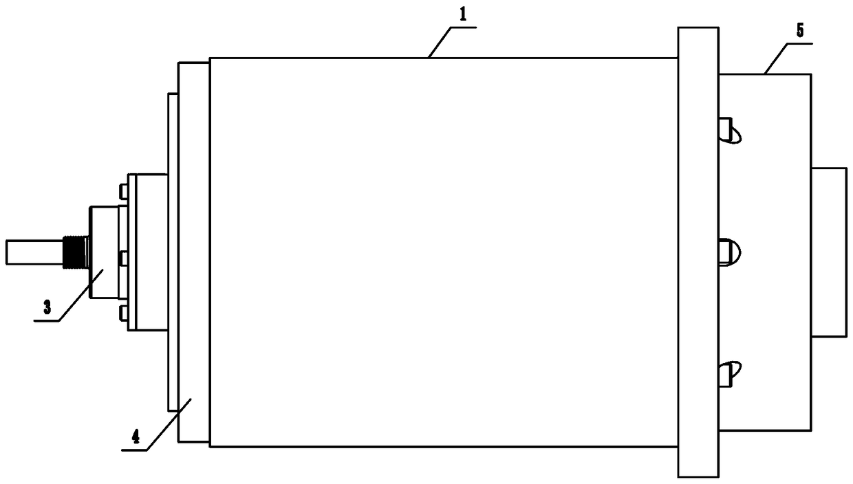
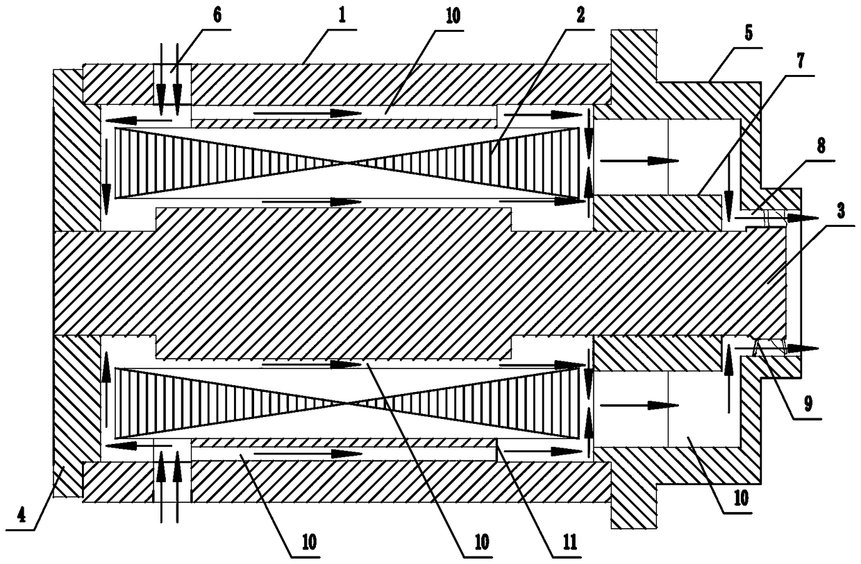
[0036] like figure 1 and figure 2 As shown, the present invention includes a machine base 1, a stator 2, and a rotor 3. The two ends of the machine base 1 are fixedly connected to the front end cover 4 and the rear end cover 5 by bolts respectively, and the position of the machine base 1 near the front end cover 4 is provided with multiple The first air inlet 6 (only two of the upper end and the lower end are shown in the figure), the rear end cover 5 is fixedly connected with the positioning sleeve 7, the center of the rear end cover 5 is provided with an air outlet 8, and the rotor 3 One end passes through the positioning sleeve 7 and fixes the fan 9 coaxially. The fan 9 is located in the air outlet 8. An air duct 10 is arranged between the stator 2 and the machine base 1, the front end cover 4, the rear end cover 5 and the rotor 3. , the inner side of the base 1 is provided with a connecting part 11, the outer wall of the stator 2 is in close contact with the connecting p...

Embodiment 2

[0038] like image 3 and Figure 4As shown, the present invention includes a machine base 1, a stator 2, and a rotor 3. The two ends of the machine base 1 are fixedly connected to the front end cover 4 and the rear end cover 5 by bolts respectively, and the position of the machine base 1 near the front end cover 4 is provided with multiple The first air inlet 6 (only two of the upper end and the lower end are shown in the figure), the rear end cover 5 is fixedly connected with the positioning sleeve 7, the center of the rear end cover 5 is provided with an air outlet 8, and the rotor 3 One end passes through the positioning sleeve 7 and fixes the fan 9 coaxially. The fan 9 is located in the air outlet 8. An air duct 10 is arranged between the stator 2 and the machine base 1, the front end cover 4, the rear end cover 5 and the rotor 3. , the inner side of the base 1 is provided with a connecting part 11, the outer wall of the stator 2 is in close contact with the connecting pa...

Embodiment 3

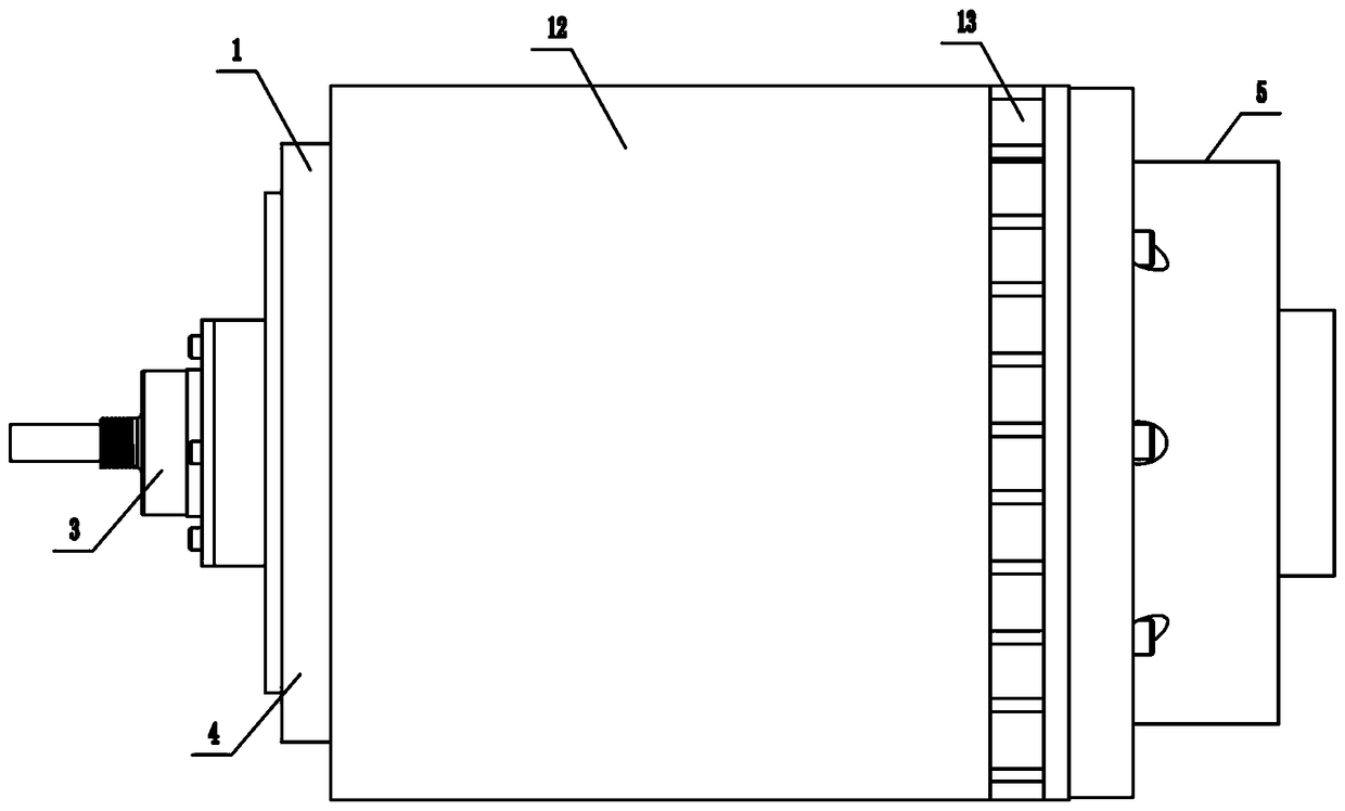
[0041] The structure of this embodiment is basically the same as that of Embodiment 2, the difference is: as Figure 5 and Image 6 As shown, a plurality of connecting ribs 15 are arranged between the positioning shaft sleeve 7 and the rear end cover 5, and the connecting ribs 15 are structures with thinner sides and a thicker middle; Under the premise, the structure of the connecting rib is improved, and the connecting rib is designed to be thin on both sides and thick in the middle, such as Figure 4 The shuttle-like structure shown can effectively reduce the wind resistance of the connecting ribs and speed up the air flow.


PUM


Abstract

The invention belongs to the technical field of electric equipment, and particularly relates to a ventilated electric motor. The ventilated electric motor comprises a base, a stator and a rotor. A front end cover and a rear end cover are arranged at two ends of the base respectively. A plurality of first air inlets are arranged at the position, close to the front end cover, of the base. A positioning shaft sleeve is arranged in the rear end cover. An air outlet is arranged at the center of the rear end cover. One end of the rotor penetrates the positioning shaft sleeve to fasten a fan coaxially. The fan is located in the air outlet. An air duct is arranged between the stator and each of the base, the front end cover, the rear end cover and the rotor. A connection component is arranged on the inner side of the base. The outer wall of the stator is in close touch connection with the connection component. The ventilated electric motor has the advantages that structures of the base, the stator and the rotor are improved, and the air ducts are reversed in the electric motor, around the stator and around the rotor, so that air cooling of the surfaces of the rotor and the stator is realized, and cooling effect is obvious.

Description

technical field [0001] The invention belongs to the technical field of electric equipment, and in particular relates to a ventilated motor. Background technique [0002] The motor is an electric device that converts electrical energy into mechanical energy, but during use, the temperature of the motor will increase for the following reasons: [0003] 1. The coil has resistance, and the current flows through the power loss; [0004] 2. The magnetic field of the iron core has a "hysteresis loop", and a part of the magnetic energy converted from electric energy continues to be converted into heat energy; [0005] 3. There are eddy currents in the iron core, and a part of the magnetic energy transformed by electric energy becomes electric current and then heat energy; [0006] 4. There is friction between the mechanical rotating parts, and part of the kinetic energy converted from electric energy continues to be converted into heat energy; [0007] The long-term heating of th...

Claims


Application Information

Patent Timeline
Patent Type & Authority Applications(China)
IPC IPC(8): H02K9/06H02K1/18H02K1/20H02K9/26H02K5/10H02K5/04
CPCH02K9/06H02K1/185H02K1/20H02K5/04H02K5/10H02K9/26
Inventor 杨立超柳鑫王瑞敏
Owner HENAN BAOTIAN ELECTROMECHANICAL SCI & TECH
Why Eureka
Try Eureka