
Pneumatic concentrating machine

A technology for wind-powered concentrators and concentrates, which is used in solid separation, separation of solids from solids by air flow, chemical instruments and methods, etc., can solve the problems of high work intensity, irregular replacement of consumables, and low recovery rate, etc. To achieve the effect of large separation particle size range, strong separation process and large particle size range

Inactive Publication Date: 2018-06-15
KUNMING UNIV OF SCI & TECH
View PDF6 Cites 0 Cited by
  • Summary
  • Abstract
  • Description
  • Claims
  • Application Information

AI Technical Summary

Problems solved by technology

Shape beneficiation is based on the different shapes of mica crystals and gangues, and the ability to pass through the sieve gaps and holes of the sieve during screening, so that mica and gangues are separated; Sieve; its disadvantage is that heavy minerals and light minerals are not easy to separate, and the phenomenon of mineral mixing is serious
[0007] To sum up, the traditional mica beneficiation methods and equipment mainly have the following two major problems: 1. It is only suitable for minerals with large particle size, resulting in serious waste of resources, low production capacity, low recovery rate, and high cost; 2. Processing The quantity is small, the equipment is large, the process is discontinuous, and it is difficult to large-scale and large-scale production, resulting in irregular replacement of consumables, high work intensity, and high sorting costs

Method used


Image

  • Pneumatic concentrating machine

Examples


Embodiment 1

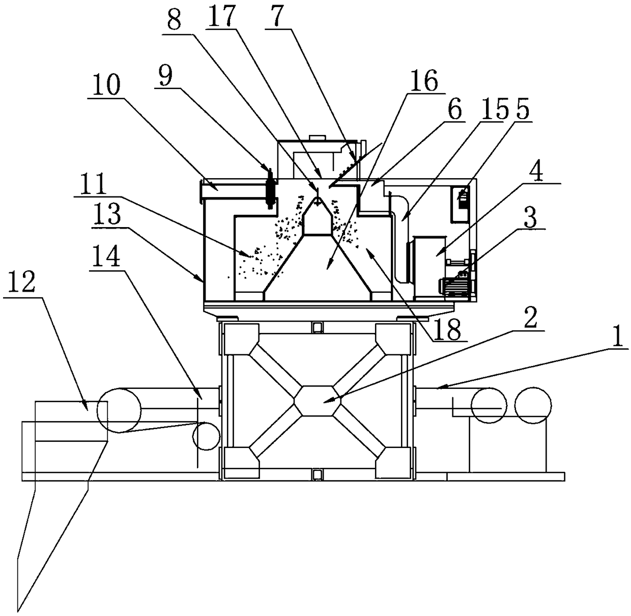
[0040] The wind power concentrator described in this embodiment is used for sorting all kinds of ores in the dressing plant, see figure 1, including tailings belt conveyor 1, bracket 2, motor 3, fan 4, frequency converter 5, air chamber 6, feeding regulating plate 7, material distribution regulating plate 8, grid 9, dust removal connecting pipe 10, concentrate buffer bin 11. Hopper 12, machine body 13, concentrate belt conveyor 14, air inlet pipe 15, conical distribution hopper 16, sorting chamber 17 and tailings buffer bin 18, the lower part of the body 13 is provided with a bracket 2, the body 13 A motor 3 is arranged inside, the motor 3 is connected to the fan 4 shaft, the motor 3 is connected to the frequency converter 5, the air outlet of the fan 4 communicates with the air chamber 6 through the air inlet pipe 15, and the air chamber 6 is located at One side of the sorting chamber 17, the grid 9 is located on the other side of the sorting chamber 17, the grid 9 is located...

Embodiment 2

[0057] The wind power concentrator described in this embodiment is used for waste recycling, including a tailings belt conveyor 1, a bracket 2, a motor 3, a fan 4, a frequency converter 5, an air chamber 6, a feeding adjustment plate 7, and a material distribution adjustment plate 8 , Grid 9, dust removal connecting pipe 10, concentrate buffer bin 11, hopper 12, body 13, concentrate belt conveyor 14, air inlet pipe 15, conical sub-hopper 16, separation chamber 17 and tailings buffer bin 18.

[0058] Compared with Embodiment 1, for the description of the structure of the wind-force concentrator in this embodiment, the similarities will not be repeated.

[0059] The use case 7 described below is a supplementary description of the second embodiment.

[0060] Scenario 7: Sorting and recycling of waste electronic devices

[0061] The resources that can be recovered from waste electronic devices mainly include inorganic materials and organic materials. Inorganic materials include ...


PUM


Abstract

The invention discloses a pneumatic concentrating machine especially suitable for sorting of mica. The lower portion of a machine body of the pneumatic concentrating machine is provided with a support. The machine body is internally provided with a motor. The motor is in shaft connection with a draught fan. The motor is connected with a frequency converter. An air outlet of the draught fan communicates with an air chamber through an air inlet pipe. The air chamber is located on one side of a sorting chamber. A grid is located on the other side of the sorting chamber. The grid and the air chamber are located on the same horizontal line. The sorting chamber is internally provided with a tapered material distribution hopper. The top of the tapered material distribution hopper is provided witha material distribution adjusting plate. The top of the sorting chamber is provided with a feeding adjusting plate. The two sides of the bottom of the sorting chamber are provided with a concentratesurge bunker and a gangue surge bunker correspondingly. The pneumatic concentrating machine is large in sorting particle size range, intensive in sorting process, high in sorting efficiency, capable of reducing product impurities and increasing the recovering rate, capable of sorting mica and other ores and suitable for agriculture, the light industry, waste recovering and other different fields.

Description

technical field [0001] The invention relates to mineral processing equipment, in particular to a wind-powered mineral processing machine, which is especially suitable for mica separation and belongs to the technical field of mining machinery and equipment. Background technique [0002] Wind beneficiation belongs to gravity beneficiation method. For a long time, gravity beneficiation has mostly been based on wet gravity separation (with water as the medium). Wet gravity separation equipment not only has many types, strong adaptability, but also has better and better performance. But at the same time, wind power beneficiation without water has always been a field of exploration. [0003] Wind beneficiation is the process of separating mineral raw materials according to the difference in mineral density in the air medium. The particle size and shape of the particles also affect the separation. Compared with wet gravity separation in water medium, wind power dressing does not ...

Claims


Application Information

Patent Timeline
Patent Type & Authority Applications(China)
IPC IPC(8): B07B7/01B07B11/02B07B11/06
CPCB07B7/01B07B11/02B07B11/06
Inventor 叶国华郎剑涛郎启斌项鹏志路璐童雄胡艺博
Owner KUNMING UNIV OF SCI & TECH
Learn More