Energy-saving type corrodible waste disposal apparatus

A waste treatment equipment and energy-saving technology, applied in chemical instruments and methods, solid waste removal, transportation and packaging, etc., can solve problems such as excessive use of valve space, inconvenient opening and closing of sealed valves, manual scraping, etc. Achieve the effect of improving processing efficiency, realizing automatic operation, and saving valve switching.

Pending Publication Date: 2018-06-15
ZHEJIANG HUALI ENVIRONMENTAL TECH CO LTD
View PDF0 Cites 0 Cited by
  • Summary
  • Abstract
  • Description
  • Claims
  • Application Information

AI Technical Summary

Problems solved by technology

[0006] 1. Manual intervention is required for feeding, and single-person control cannot be realized;
[0007] 2. No squeezing function, high energy consumption per unit of waste, and long cycle of corrosive waste treatment;
[0008] 3. It is difficult to discharge the material, and it needs manual picking;
[0012] 2. It is inconvenient to switch and seal the valve because it needs to be pressed by an external force perpendicular to the valve;
[0013] 3. The force is uneven, often the hinge end is pressed to death, and the pressure away from the hinge end is looser, and the sealing effect is getting worse from the hinge end;
[0014] 4. The installation requirements are high, and the use space of the valve occupies too much;
[0015] 5. The sealing effect is not ideal, and the sealing time is not long
The current clamshell pressing device is either a separate automatic clamshell device, or a separate clamshell device, or the clamshell device is installed on the automatic clamshell, and the clamshell must also move when pressing the material; the whole is relatively heavy, and the drive device is complicated. overload

Method used


Image

  • Energy-saving type corrodible waste disposal apparatus
  • Energy-saving type corrodible waste disposal apparatus
  • Energy-saving type corrodible waste disposal apparatus

Examples


Embodiment Construction

[0043] The present invention will be further described below in conjunction with the accompanying drawings and specific embodiments, but the scope of protection of the present invention is not limited thereto.

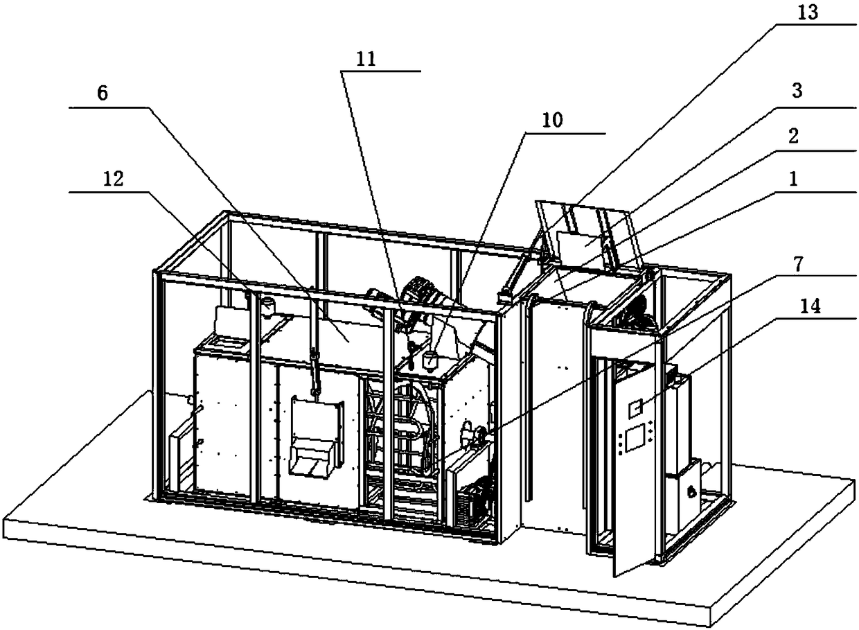
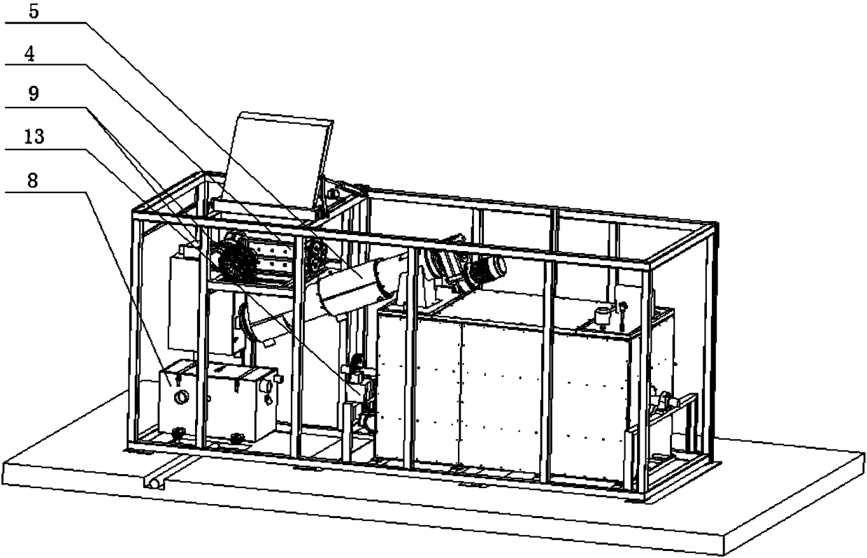
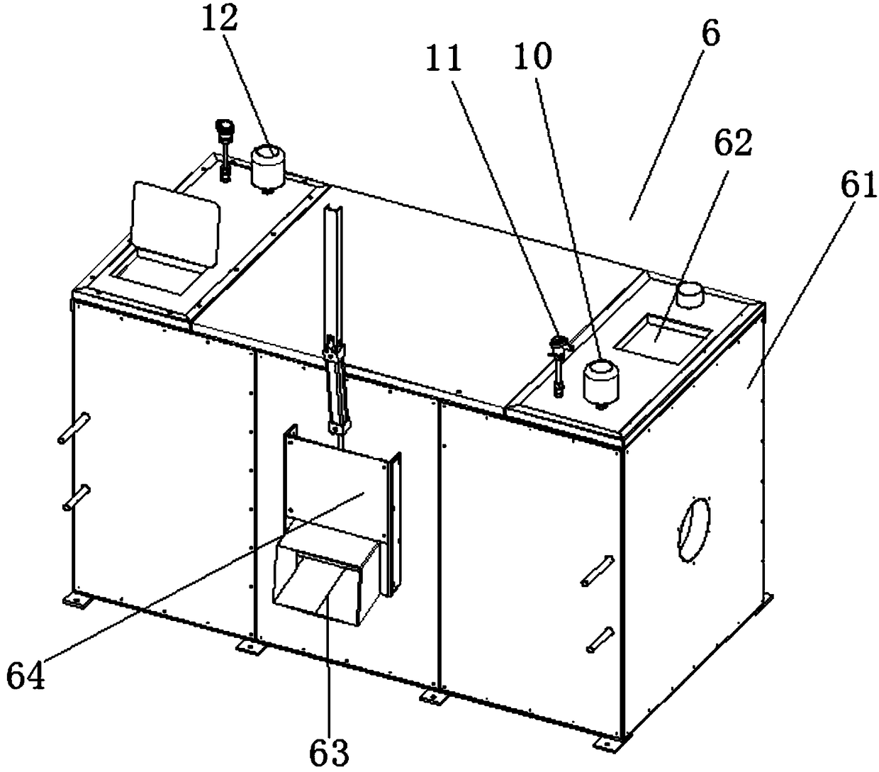
[0044] refer to Figure 1-2 , an energy-saving corrodible garbage treatment equipment, which includes an electric hoist 1, a feed hopper 2, a pressing device 3, a shredder 4, a squeezing machine 5, a fermentation tank 6, a stirring heating device 7, and an oil-water separation device 8 and exhaust gas treatment device 9, the electric hoist 1 is arranged on one side of the feed hopper 2, the pressing device 3 is located above the feed hopper 2, and the shredder is located below the feed hopper 2; the squeezer 5 is provided with Feed inlet, discharge port, liquid outlet and gas outlet, the feed inlet of extruder 5 communicates with the discharge port of shredder 4, and the discharge port of extruder 5 is positioned at the feed inlet top of fermentation box 6 , the liqui...


PUM


Abstract

The invention relates to an energy-saving type corrodible waste disposal apparatus. The energy-saving type corrodible waste disposal apparatus comprises a motor hoist, a feeding hopper, a material pressing device, a shredding machine, a squeezing machine, a fermentation box, a mixing and heating device, an oil and water separation device and a waste gas treatment device. The motor hoist is arranged on one side of the feeding hopper. The material pressing device is located above the feeding hopper. The shredding machine is located below the feeding hopper. The squeezing machine is provided witha feeding inlet, a discharging outlet, a fluid outlet and a gas outlet. The feeding inlet of the squeezing machine communicates with the discharging outlet of the shredding machine. The discharging outlet of the squeezing machine is located above the feeding inlet of the fermentation box. The fluid outlet of the squeezing machine communicates with the oil and water separation device. The fermentation box is provided with a gas outlet which communicates with the waste gas treatment device. The mixing and heating device is arranged in the fermentation box. According to the energy-saving type corrodible waste disposal apparatus, because the shredding machine and the squeezing machine are adopted, the corrodible waste enters the fermentation box after being subjected to shredding and water squeezing, the energy consumed by the fermentation box is reduced, and the treatment efficiency is improved.

Description

technical field [0001] The invention relates to a garbage treatment device, in particular to an energy-saving corrodible garbage treatment equipment. Background technique [0002] Garbage reduction means that most wastes are loose and bulky, which not only increases transportation costs, but also occupies a large landfill site. Based on this, solid waste is compressed or liquid waste is concentrated, or waste is harmlessly incinerated and burned to ashes. Reduce the volume to less than 1 / 10 for transportation to landfill. [0003] The reduction of solid waste requires physical means (such as crushing, compression, drying, evaporation, incineration, etc.) or biochemical effects (such as oxidation, digestion, decomposition, absorption, etc.) and chemical effects such as pyrolysis and gasification to reduce its volume. , Accelerate the process of its natural purification. [0004] At present, in the process of waste reduction treatment, physical means such as compaction and c...

Claims


Application Information

Patent Timeline
Patent Type & Authority Applications(China)
IPC IPC(8): B09B3/00B09B5/00
CPCB09B3/00B09B5/00B09B3/40
Inventor 潘婷徐建钢蔡雷军宣柯锋
Owner ZHEJIANG HUALI ENVIRONMENTAL TECH CO LTD
Why Eureka
Try Eureka