

A feeding assistance robot
A robot and gripper technology, applied in the field of diet care robots, can solve the problems of small working space, poor flexibility and positioning accuracy, and less degrees of freedom, and achieve good movement coordination, high positioning accuracy, and large movement space. Effect
- Summary
- Abstract
- Description
- Claims
- Application Information
AI Technical Summary
Problems solved by technology
Method used
Image

Examples
Embodiment 1
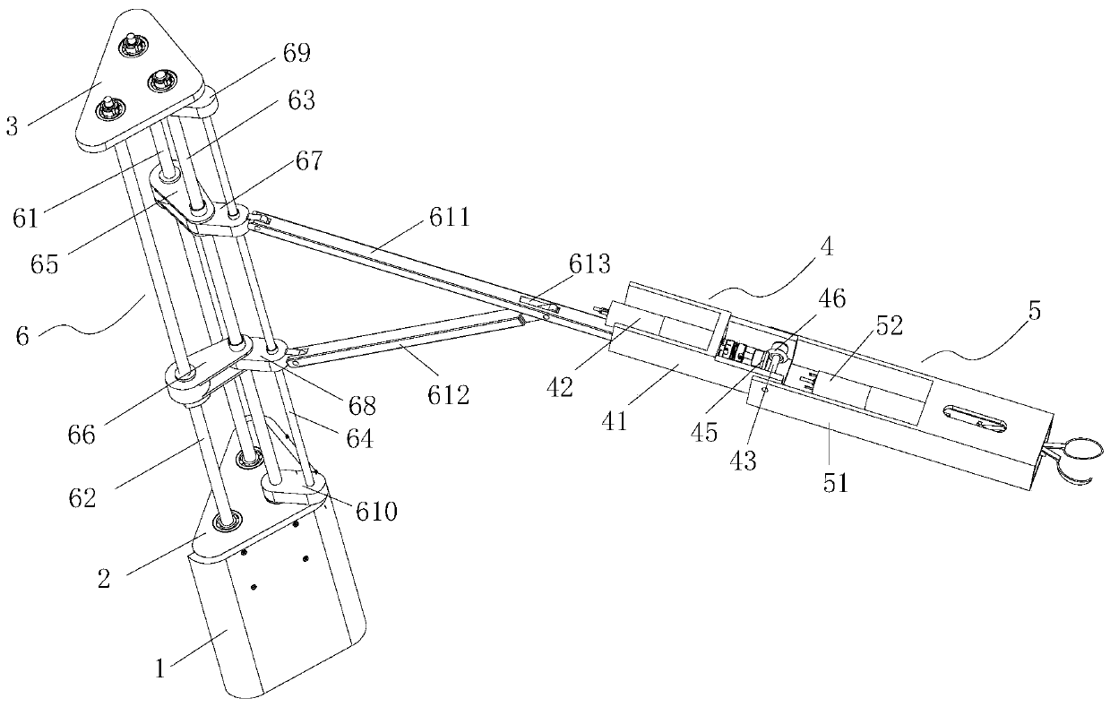
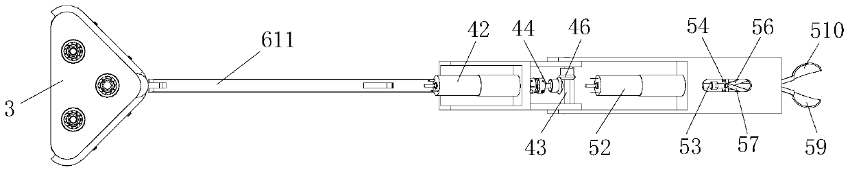
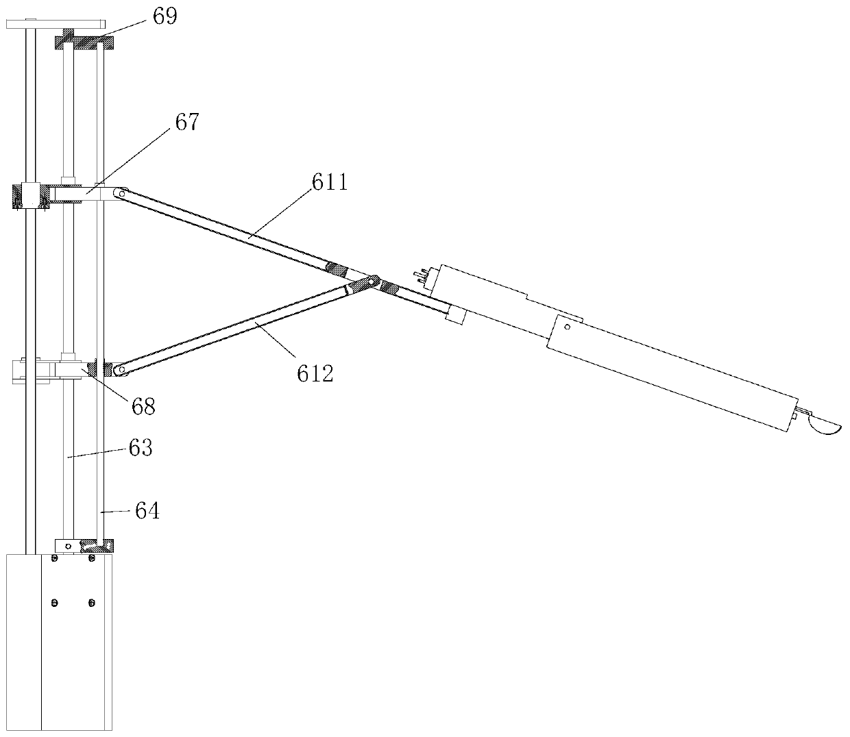
[0033] Such as Figure 1 to Figure 4As shown, a feeding assistance robot includes a gripper 5, a mechanical arm 4, and a main body rotating lifting device 6 for driving the gripper 5 and the robotic arm 4 to lift, move back and forth, and swing left and right.
[0034] The gripper 5 includes a gripper housing 51 and a spoon for gripping food arranged at the front end of the gripper housing 51. The gripper housing 51 is hinged with the front end of the mechanical arm 4 and can be positioned relative to the front end of the mechanical arm 4. Described mechanical arm 4 swings up and down.
[0035] The spoon includes a first half scoop 59 and a second half scoop 510, and the first half scoop 59 and the second half scoop 510 cooperate with each other to complete the picking and placing of food. The clamper housing 51 is provided with a clamping driving device for driving the first and second half spoons to separate from each other and to move closer to each other. The clamping dr...
Embodiment 2
[0050] The structure, principle and composition of this embodiment are basically the same as those of the above-mentioned embodiment 1, the only difference lies in the installation position of the rotation driving mechanism and the installation position of the gripper on the arm frame.
[0051] Such as Figure 5 and Figure 6 As shown, in this embodiment 2, the clamper 5 is integrally installed in the arm frame 41 and is in a suspended state, and the clamper housing 51 is rotationally connected with the arm frame 41 through the first transmission shaft 43, so Said rotary drive mechanism comprises a third motor 47, the third motor 47 is arranged on one side of the boom 41, the axis of the output shaft of the third motor 47 is parallel to the axis of the first transmission shaft 43, and the first transmission shaft 43 The rotation is driven by the third motor 47 , thereby driving the holder housing 51 to swing up and down relative to the boom 41 .
[0052] The present inventio...
PUM
 Abstract
Description
Claims
Application Information