
Clothing production line assembly line cloth waste treating device

A processing device and production line technology, applied in the field of garment production, can solve the problems of time-consuming and laborious, affecting the progress of production and processing, affecting the efficiency of production and processing, etc.

Active Publication Date: 2018-06-15
WENZHOU POLYTECHNIC
View PDF8 Cites 0 Cited by
  • Summary
  • Abstract
  • Description
  • Claims
  • Application Information

AI Technical Summary

Problems solved by technology

[0002] The production process of clothing includes cutting, sewing, ironing, packaging and other processes. During the cutting process, various scraps of different sizes will be left, and the scraps of scraps will be scattered on the assembly line or work surface of the garment processing , has brought a lot of inconvenience to the production and operators, and the leftover waste can be recycled and reused. The traditional cleaning method requires the staff to recycle it by themselves, which is very time-consuming and laborious, which affects the production and processing progress, thus affecting the production and processing efficiency. The production and processing cost of the enterprise is increased. The existing device can collect the scraps on the work surface through the fan, but the staff needs to hold the air duct to absorb the rags. The work efficiency has not been improved. Specialized personnel place the collected scraps in a unified way to facilitate the processing of rags, but the process is still too cumbersome

Method used


Image

  • Clothing production line assembly line cloth waste treating device
  • Clothing production line assembly line cloth waste treating device
  • Clothing production line assembly line cloth waste treating device

Examples


Embodiment Construction

[0013] In order to make the purpose, technical solutions and advantages of the embodiments of the present invention clearer, the technical solutions in the embodiments of the present invention will be clearly and completely described below in conjunction with the drawings in the embodiments of the present invention. Obviously, the described embodiments It is a part of embodiments of the present invention, but not all embodiments. Based on the embodiments of the present invention, all other embodiments obtained by persons of ordinary skill in the art without creative efforts fall within the protection scope of the present invention.

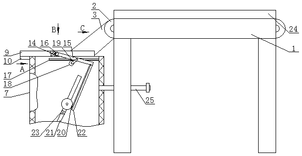
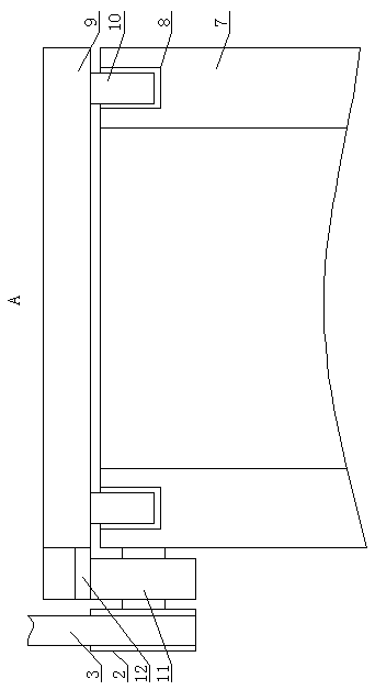
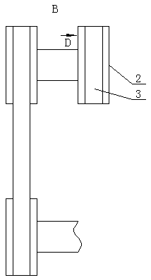
[0014]A garment production line rag processing device, as shown in the figure, includes a workbench 1, and pulleys 2 are fixedly installed on both sides of the back of the workbench 1, and the two pulleys 2 are connected by a conveyor belt 3, and one of the pulleys The back side of 2 is provided with cylindrical groove 4, and several wedge-shaped ...


PUM


Abstract

The invention discloses a clothing production line assembly line cloth waste treating device which comprises a workbench. Belt wheels are fixedly installed on the two sides of the back face of the workbench correspondingly. The two belt wheels are connected through a conveying belt, the back face of one belt wheel is provided with a cylindrical groove, multiple wedge-shaped blocks are fixedly installed on the inner wall of the cylindrical groove, the cylindrical groove is provided with a rotating disc through a bearing, multiple same wedge-shaped blocks are installed on the periphery of the rotating disc through torsion springs, the wedge-shaped blocks on the rotating disc and the wedge-shaped blocks in the cylindrical groove are arranged in a staggered mode. By means of mutual matching ofan air pipe, a top cover, a sliding groove and a sliding strip, matching between the air pipe and the top cover can be tighter, air noise of the air pipe can be reduced when the top cover is closed to prevent from affecting communication of workers, meanwhile, listening of workers is protected against damage, sucking force of the main air pipe will not be dispersed, the main air pipe can keep sucking force strong enough so as to suck cloth waste into the cloth waste treating device for centralized treatment, and cloth waste collection efficiency can be improved.

Description

technical field [0001] The invention belongs to the field of garment production, in particular to a garment production line rag processing device. Background technique [0002] The production process of clothing includes cutting, sewing, ironing, packaging and other processes. During the cutting process, various scraps of different sizes will be left, and the scraps of corners will be scattered on the assembly line or work surface of the garment processing , has brought a lot of inconvenience to the production and operators, and the corner waste can be recycled and reused. The traditional cleaning method requires the staff to recycle it by themselves, which is very time-consuming and laborious, which affects the production and processing progress, thus affecting the production and processing efficiency. The production and processing cost of the enterprise is increased. The existing device can collect the scraps on the work surface through the fan, but the staff needs to hold...

Claims


Application Information

Patent Timeline
Patent Type & Authority Applications(China)
IPC IPC(8): B65G53/24B65G53/44
CPCB65G53/24B65G53/44
Inventor 吴国智
Owner WENZHOU POLYTECHNIC
Learn More