Phase-locked loop circuit, system with multiple phase-locked loops and output phase synchronization method thereof

A phase-locked loop and circuit technology, applied in the direction of electrical components, automatic power control, etc., can solve the problem of delay error, the local oscillator signal cannot keep the same phase, etc., to avoid phase inconsistency, keep the phase consistent, and improve system performance. Effect

Active Publication Date: 2018-06-15
SHANGHAI JIAO TONG UNIV
View PDF6 Cites 10 Cited by
  • Summary
  • Abstract
  • Description
  • Claims
  • Application Information

AI Technical Summary

Problems solved by technology

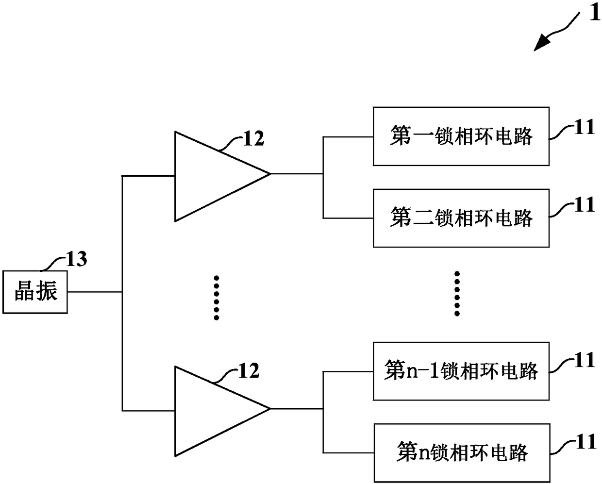
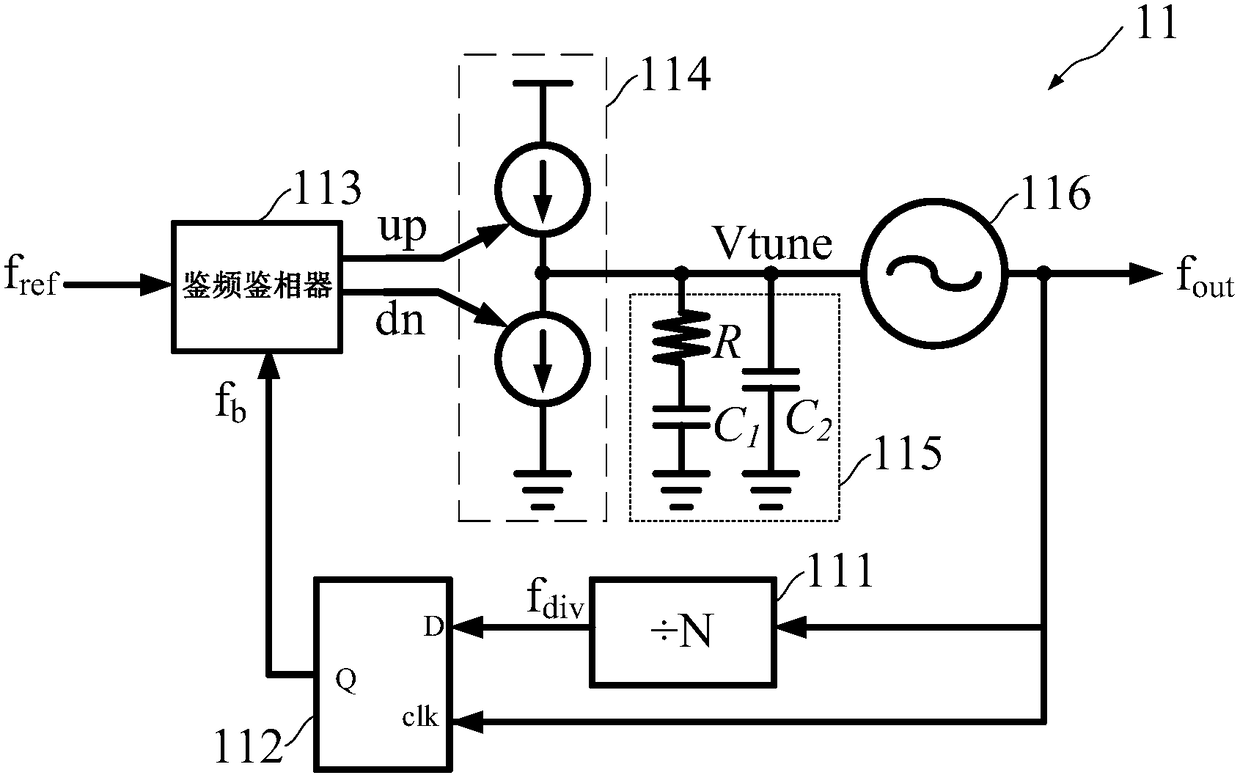
However, using the traditional Type-II phase-locked loop structure, the frequency divider output of a single phase-locked loop can be aligned with the reference clock phase. There are different degrees of delay errors in the phases of the phase-locked loop frequency divider output signal and the voltage-controlled oscillator output signal. As a result, even if the crystal oscillator signals input to all transceiver phase-locked loops have the same phase, due to the delay of the frequency divider The relationship between time and time is different, and finally the local oscillator signal provided by each transceiver cannot maintain the same phase

Method used


Image

  • Phase-locked loop circuit, system with multiple phase-locked loops and output phase synchronization method thereof
  • Phase-locked loop circuit, system with multiple phase-locked loops and output phase synchronization method thereof
  • Phase-locked loop circuit, system with multiple phase-locked loops and output phase synchronization method thereof

Examples


Embodiment Construction

[0044] Embodiments of the present invention are described below through specific examples, and those skilled in the art can easily understand other advantages and effects of the present invention from the content disclosed in this specification. The present invention can also be implemented or applied through other different specific implementation modes, and various modifications or changes can be made to the details in this specification based on different viewpoints and applications without departing from the spirit of the present invention.

[0045] see Figure 1 to Figure 5 . It should be noted that the diagrams provided in this embodiment are only schematically illustrating the basic idea of ​​the present invention, and only the components related to the present invention are shown in the diagrams rather than the number, shape and shape of the components in actual implementation. Dimensional drawing, the type, quantity and proportion of each component can be changed arb...


PUM


Abstract

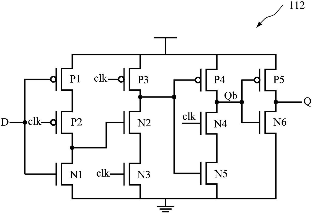
The invention provides a phase-locked loop circuit, a system with multiple phase-locked loops and an output phase synchronization method thereof. The invention includes a frequency divider for frequency division of an output signal, a sampler which samples the frequency-divided signal based on the output signal to obtain a feedback signal to ensure that the phase of the feedback signal is consistent with the phase of the output signal, a phase frequency detector which determines the phase difference between the feedback signal output by the sampler and the input crystal oscillator signal to generate a pulse signal, a charge pump which generates tuning voltages based on the pulse signal, and a voltage controlled oscillator which adjusts the frequency of the output signal based on the tuningvoltages. In the invention, a sampling method is adopted to realize the phase consistency of the feedback signal and the output signal of the phase-locked loop circuits. Thus the phase consistency between the output signal and the input crystal oscillator signal is greatly improved. Besides, in the system with multiple phase-locked loops, the phase of the output signals of all phase-locked loop circuits is ensured to be consistent so as to improve the system performance.

Description

technical field [0001] The invention relates to the technical field of wireless communication integrated circuits, in particular to a phase-locked loop circuit, a multi-phase-locked loop system and an output phase synchronization method thereof. Background technique [0002] Phase locked loop (phase locked loop, PLL), as the name implies, is a phase-locked loop, which is a typical feedback control circuit. It uses an external input reference signal to control the frequency and phase of the internal oscillation signal of the loop, and realizes the output signal frequency. Automatic tracking of input signal frequency, generally used in closed-loop tracking circuits. The phase-locked loop is a method to stabilize the frequency in radio transmission. In order to keep the frequency unchanged, it is required that the phase difference between the crystal oscillator and the phase-locked loop output signal does not change. If there is a change in the phase difference, it is related t...

Claims


Application Information

Patent Timeline
Patent Type & Authority Applications(China)
IPC IPC(8): H03L7/07H03L7/081H03L7/18
CPCH03L7/07H03L7/081H03L7/18
Inventor 丁力刘力僮金晶周健军
Owner SHANGHAI JIAO TONG UNIV
Why Eureka
Try Eureka