Microwave photonics based multi-channel signal transmission system for aperture synthesis radiometer

A radiation signal and synthetic aperture technology, applied in the field of microwave remote sensing, can solve the problems of heavy weight, increased antenna arm volume, and increased system weight, and achieve strong electromagnetic isolation, strong temperature stability, and overcome limitations

Active Publication Date: 2014-03-26
XIAN INSTITUE OF SPACE RADIO TECH
View PDF4 Cites 4 Cited by
  • Summary
  • Abstract
  • Description
  • Claims
  • Application Information

AI Technical Summary

Problems solved by technology

[0004] The disadvantages of the above method are: (1) For the multi-channel digital optical fiber transmission mode, the collectors are distributed on each receiving unit, which increases the difficulty of clock synchronization and cannot guarantee the high-amplitude phase consistency requirements during the transmission process. It needs to be solved by calibration; due to the use of distributed signal acquisition method, the size of the antenna arm increases and the weight of the system increases
(2) For the multi-channel radio frequency signal transmission mode of the coaxial cable, due to the different transmission paths of the multi-channel signal, its amplitude and phase consistency are not guaranteed; the coaxial cable is large in size and heavy in weight, which is not conducive to multi-channel signal transmission. Transmission use; coaxial cable bending radius and volume limitations make it difficult to deploy the antenna arm on orbit

Method used


Image

  • Microwave photonics based multi-channel signal transmission system for aperture synthesis radiometer
  • Microwave photonics based multi-channel signal transmission system for aperture synthesis radiometer
  • Microwave photonics based multi-channel signal transmission system for aperture synthesis radiometer

Examples


Embodiment Construction

[0020] Specific embodiments of the present invention will be further described in detail below in conjunction with the accompanying drawings.

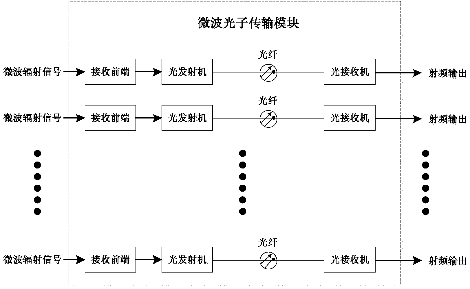
[0021] The invention provides a microwave photon-based synthetic aperture radiometer multi-channel signal transmission system, which is used to ensure the high amplitude and phase consistency of the synthetic aperture microwave radiometer multi-channel radio frequency signal transmission. Such as figure 1 A system of the present invention is shown comprising: a plurality of receive front ends, a plurality of optical transmitters, a plurality of optical fibers, and a plurality of optical receivers; wherein:

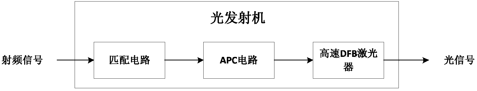
[0022] Such as figure 2 As shown, a single receiving front-end includes an antenna, an isolator and a low-noise amplifier module. The antenna adopts a microstrip antenna. The gain of the low-noise amplifier module is about 50dB, and the noise figure is <1.5dB.

[0023] The functions of the receiving front end are:

[0024] a. R...


PUM


Abstract

Disclosed is a microwave photonics based multi-channel signal transmission system for an aperture synthesis radiometer. The system comprises multi-channel receiving front ends, multi-channel optical transmitters, multi-channel optical fibers and optical receivers. The multi-channel receiving front ends receive multi-channel radio frequency microwave radiation signals through antennas, and then amplify the received signals through low-noise amplification modules. The multi-channel optical transmitters modulate the amplified radio frequency signals to light, light signals are transmitted from all the optical transmitters to the optical receivers through the multi-channel optical fibers, then the optical receivers convert the light signals into radio frequency signals to be outputted, and transmission of the multi-channel radio frequency signals of the aperture synthesis microwave radiometer is completed. By adoption of microwave photonics technology, the radio frequency signals of the distributed receiving front ends of the aperture synthesis microwave radiometer are transmitted, amplitude and phase congruency of multi-channel radio frequency transmission are improved greatly. The method is simple to implement and high in reliability, and a critical foundation is laid to future application of the aperture synthesis microwave radiometer.

Description

technical field [0001] The invention relates to a multi-channel radio frequency signal transmission system of a synthetic aperture microwave radiometer based on microwave photons, which belongs to the field of microwave remote sensing. Background technique [0002] Synthetic aperture microwave radiometer is a new type of microwave radiometer, which uses small aperture antennas to synthesize a large observation aperture, which can avoid the weight, volume and scanning requirements of large aperture antennas on the platform and difficulties in processing, and effectively It solves the contradiction between spatial resolution and observation width, and is easy for spaceborne applications. The synthetic aperture microwave radiometer needs to transmit the multi-channel receiving front-ends on each antenna arm to the central processing unit. Since the distance between multiple receiving front-ends and the central processing unit is far away, and the antenna arms need to be unfolde...

Claims


Application Information

Patent Timeline
Patent Type & Authority Applications(China)
IPC IPC(8): H04B10/2575
Inventor 李浩李一楠吕容川段崇棣沈尚宇陈文新李延明
Owner XIAN INSTITUE OF SPACE RADIO TECH
Why Eureka
Try Eureka