
Particle therapy apparatus for eye treatment

A treatment device and eye technology, applied in treatment, X-ray/γ-ray/particle irradiation therapy, equipment for testing eyes, etc., can solve problems affecting treatment time, insufficient dose rate, etc., and achieve reduced treatment time and high dose The effect of high efficiency and good comfort

Inactive Publication Date: 2018-06-19
ION BEAM APPL
View PDF6 Cites 0 Cited by
  • Summary
  • Abstract
  • Description
  • Claims
  • Application Information

AI Technical Summary

Problems solved by technology

Dose rates using this technique may also be insufficient, which further impacts treatment time

Method used


Image

  • Particle therapy apparatus for eye treatment
  • Particle therapy apparatus for eye treatment
  • Particle therapy apparatus for eye treatment

Examples


Embodiment Construction

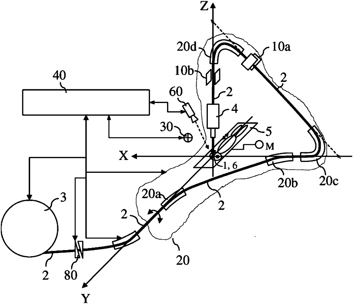
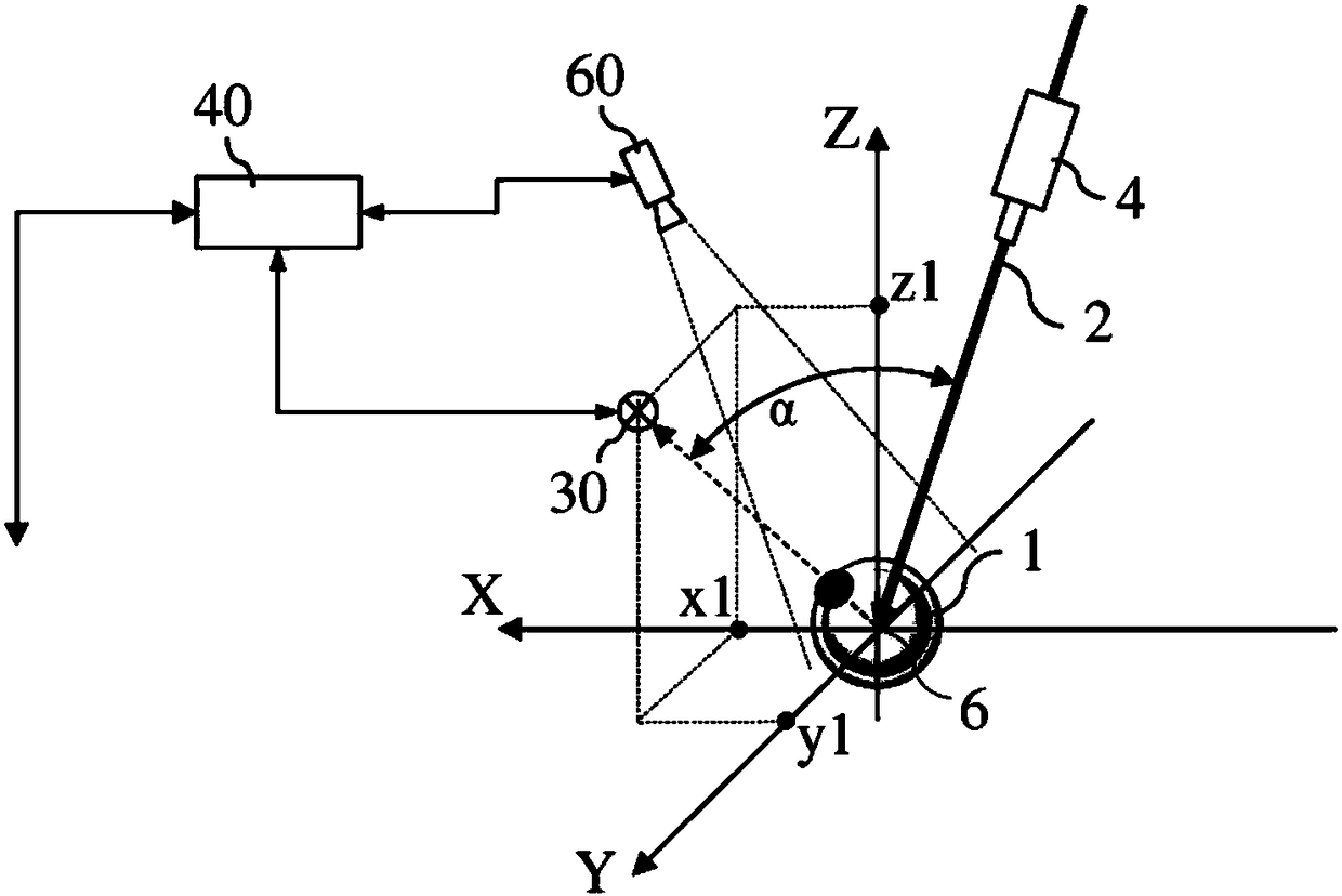
[0030] figure 1 An exemplary particle therapy device according to the invention is schematically shown. The particle therapy device is configured to irradiate a diseased part of a patient's eye (1) with a charged particle beam (2). The particle therapy device comprises a particle accelerator (3) for generating a charged particle beam (2), adapted to receive and direct the charged particle beam (2) towards a movable part of the patient's eye (1) according to different beam directions. The irradiation nozzle (4) of the , and the beam delivery system for transporting the particle beam from the particle accelerator (3) to the beam entry point (4) entering the nozzle. There are known devices to move such an irradiation nozzle (4) relative to the target, here relative to the patient's eye (1). For example, a known device is disclosed in patent publication number WO2016 / 029083, wherein the nozzle (4) can be moved to four different positions and orientations in order to Irradiate t...


PUM


Abstract

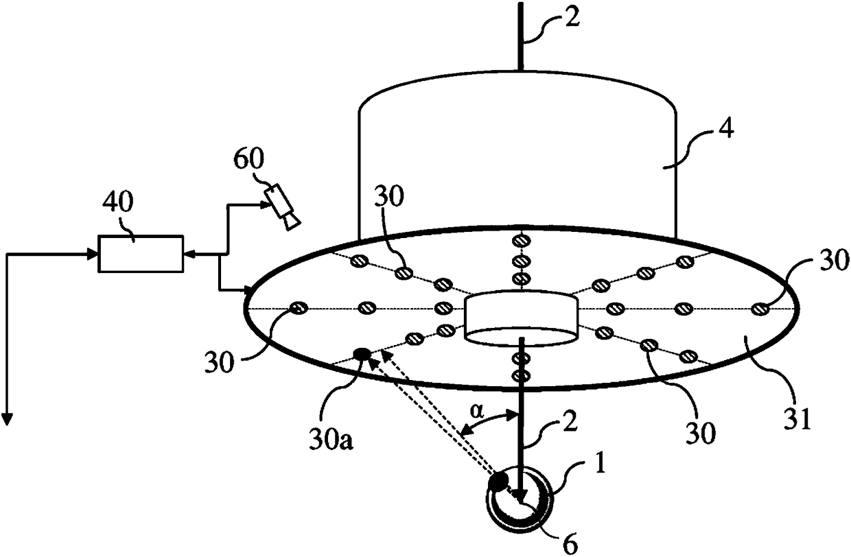
A particle therapy apparatus 1 for irradiating a diseased part of a patient's eye with a charged particle beam comprises a particle accelerator (3) to generate the particle beam 2, a movable irradiation nozzle (4) adapted to direct the charged particle beam 2 towards the patient's eye (1) according to different beam directions, and a patient support (5) adapted to receive and hold the patient in atreatment position. The apparatus further comprises a pencil beam scanning subsystem (10a, 10b) configured to scan the charged particle beam 2 over the diseased part of the patient's eye (1), a movable marker (30) arranged in such a way that it is visible by the patient while the patient is in the treatment position, and a controller (40) configured to move said marker (30) to a pre-determined and patient-specific position before starting the irradiation of the eye (1) with the particle beam (2).

Description

technical field [0001] The present invention relates to a device for irradiating a diseased part of a patient's eye with a beam of charged particles for therapeutic purposes. Background technique [0002] Particle therapy, such as proton therapy, has been used to treat ocular melanoma for more than 40 years. [0003] Due to the specific nature of the eye and ocular melanoma, known particle therapy devices for the treatment of such diseases generally utilize dedicated individual, anterior and fixed beamlines and dedicated nozzles with small apertures. They use beam-scattering techniques to deliver a wide beam that covers the target area to be irradiated. The disadvantage of these devices is that specialized equipment must be designed, manufactured, installed and operated, and such specialized devices cannot, or rarely, be used to treat other types of human tumors. Another disadvantage is that such devices may cause unwanted neutron and / or gamma radiation to the patient due ...

Claims


Application Information

Patent Timeline
Patent Type & Authority Applications(China)
IPC IPC(8): A61N5/10
CPCA61N5/1017A61N5/103A61N5/1048A61N2005/1092A61N2005/1087A61N5/1081A61B3/0091A61B3/145A61B3/0083A61N5/1047A61N5/1049A61N5/1043A61F9/007A61N5/1071A61N2005/1051A61N2005/1059A61N2005/1074A61B2090/3937A61B2090/3945
Inventor C·富恩特斯
Owner ION BEAM APPL
Learn More