Supercharge Your Innovation With Domain-Expert AI Agents!

Fixed compression and die cutting robot for printing products

A fixed and robotic technology, applied in metal processing, etc., can solve the problems of reducing processing efficiency and processing accuracy, low production efficiency, and increasing processing costs, so as to improve work efficiency and service life, avoid unstable connections, and improve processing cost effect

Inactive Publication Date: 2018-06-19
安吉腾新印刷厂
View PDF1 Cites 0 Cited by
  • Summary
  • Abstract
  • Description
  • Claims
  • Application Information

AI Technical Summary

Problems solved by technology

The structure of the vertical flat die-cutting machine is mainly divided into two parts: the body and the press frame. The die-cutting table is installed on the body. The vertical flat die-cutting machine can be divided into semi-automatic and fully automatic according to the degree of automation At present, the vertical flat die-cutting machine (Tiger Mouth) produced in China is mainly semi-automatic. The die-cutting is done by the machine, and the paper feeding and delivery are completed by a single person operating the die-cutting machine wrench. The machine utilization rate is not high. High, low production efficiency, due to the design of the wrench of the creasing die-cutting machine, even if more manpower is added to handle the above work, the workers will affect each other. One worker is operating, even if two workers are arranged, there will be interference between the positions of each other, and there will be a wait in the process of job transition. Investing in one more worker cannot reasonably shorten the working hours. In the existing technology, for example, the application number The invention patent of 201620939525.6 mainly consists of two parts: the fuselage and the press frame. The die-cutting table is installed on the fuselage. A wrench for controlling the die-cutting machine is also installed on the right side of the body base of the die-cutting machine. The wrench for controlling the die-cutting machine on the left side and the wrench for controlling the die-cutting machine on the right are connected through a U-shaped connecting rod to realize real-time linkage in the same direction. , although the structure of this invention is simple, there are many deficiencies and defects. In the existing equipment, the design of the control wrench has defects, and the control wrench requires one or more staff members to operate. While causing physical fatigue to the staff, the processing efficiency and processing accuracy are reduced, and the indentation will produce uneven stress due to manual operation, resulting in waste of printed products. In view of these situations, in order to avoid the above technical problems, there are indeed It is necessary to provide a stationary creasing and die-cutting robot for printed products to overcome the defects in the prior art

Method used


Image

  • Fixed compression and die cutting robot for printing products
  • Fixed compression and die cutting robot for printing products
  • Fixed compression and die cutting robot for printing products

Examples


Embodiment Construction

[0019] The following will clearly and completely describe the technical solutions in the embodiments of the present invention with reference to the accompanying drawings in the embodiments of the present invention. Obviously, the described embodiments are only some, not all, embodiments of the present invention. Based on the embodiments of the present invention, all other embodiments obtained by persons of ordinary skill in the art without making creative efforts belong to the protection scope of the present invention.

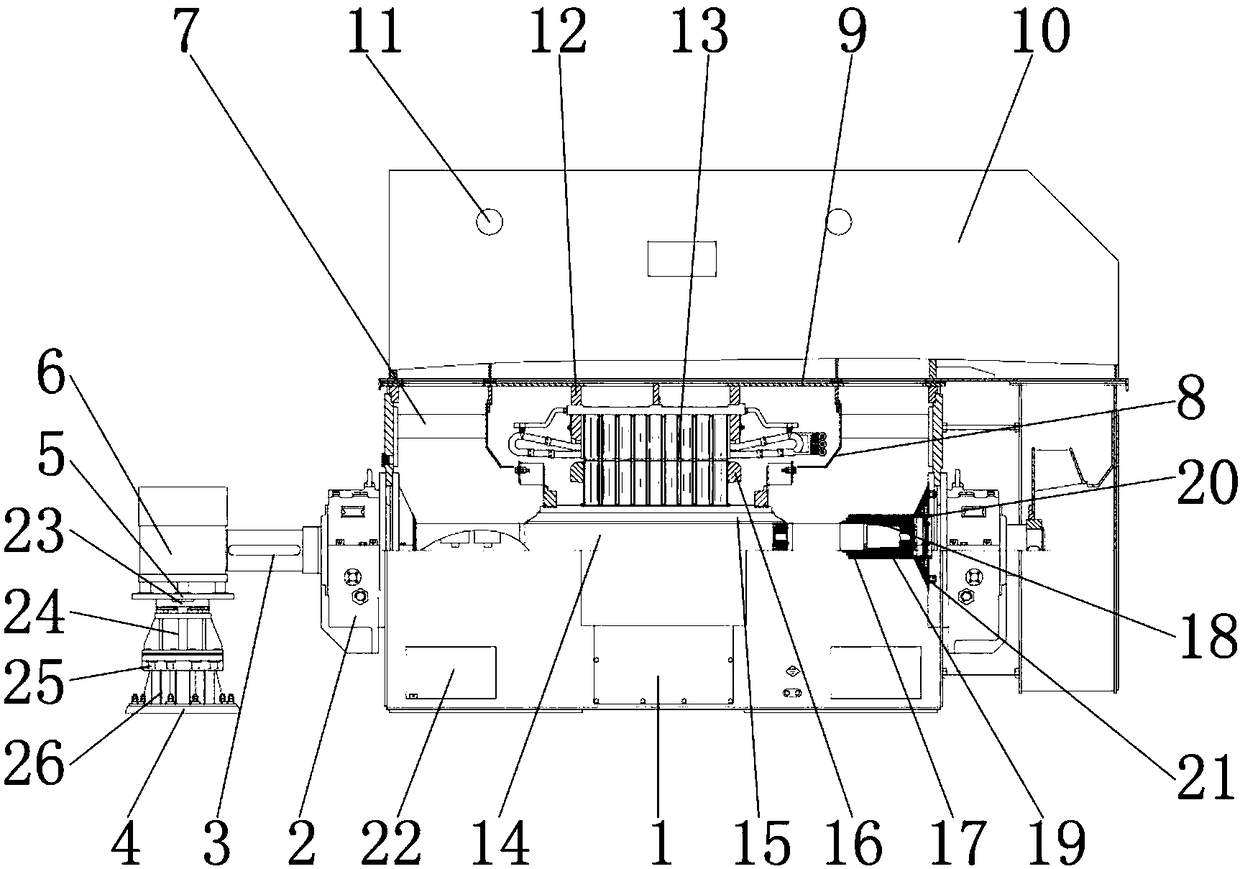
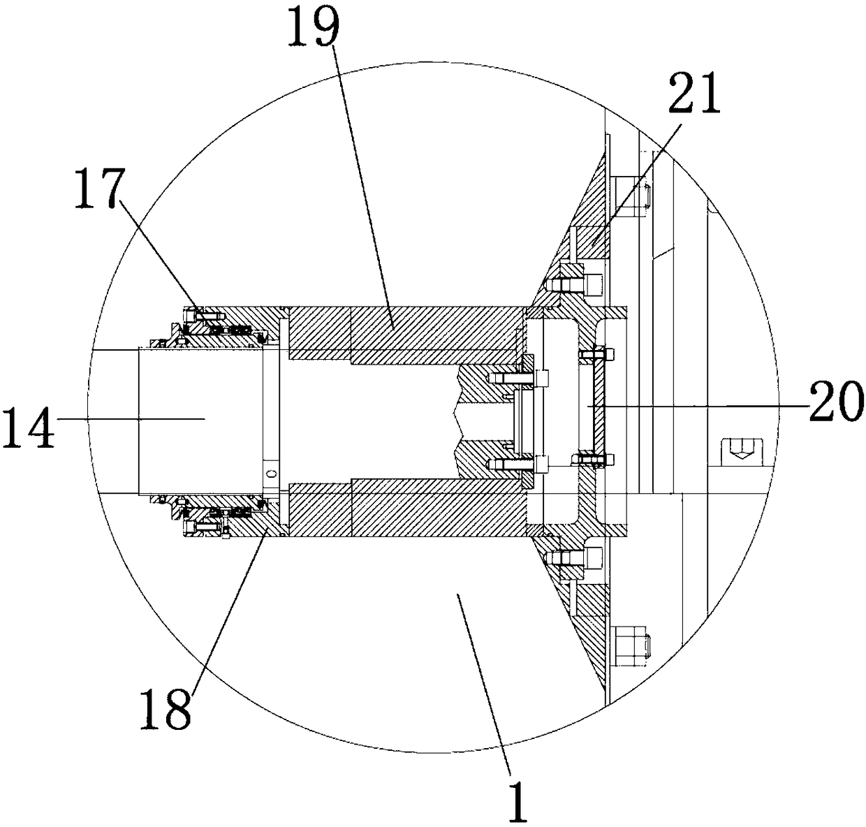
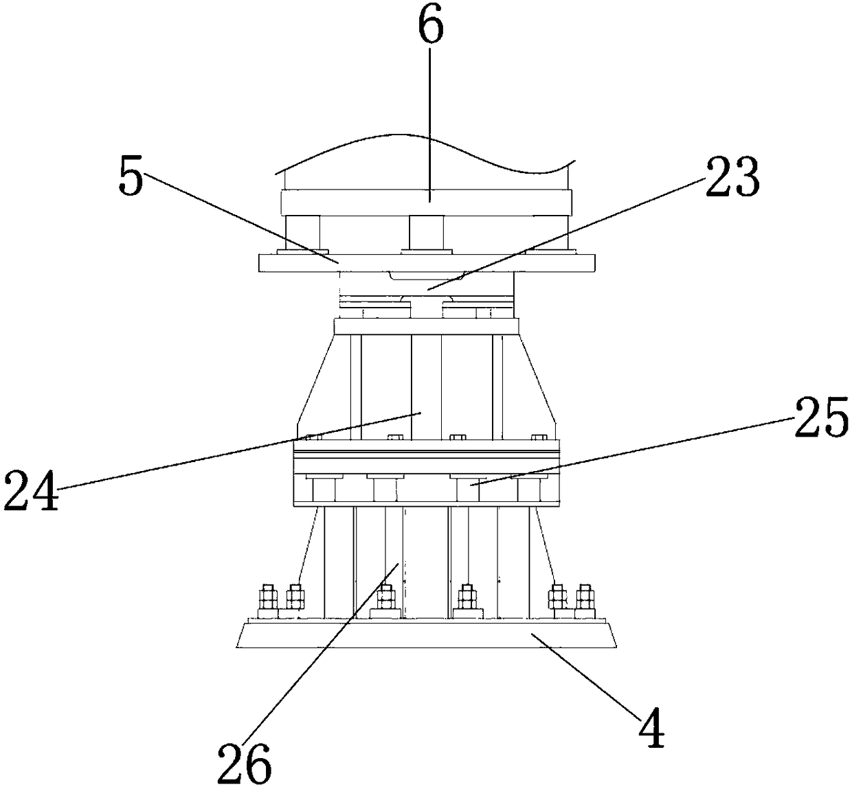
[0020] see Figure 1-3, the present invention provides a technical solution: a fixed creasing and die-cutting robot for printed products, including a box body 1 for installing a rotating rod 14, and a shield 10 is provided on the upper surface of the box body 1 for Lamp holder 11 or anti-splash are installed, lamp holder 11 is installed on the inner wall of shield 10, is used for installing light source such as lamp holder, the outer wall of lamp holder 11 is ...


PUM


Abstract

The invention discloses a fixed compression and die-cutting robot for printing products. The robot comprises a box body, the left and right sides of the outer wall of the box body are both provided with shaft brackets, the inner wall of each shaft bracket is connected with the outer wall of the box body, the inner wall of the shaft bracket is provided with a rotating rod, the outer wall of the rotating rod is connected to the inner wall of the shaft bracket, the left side of the shaft bracket is provided with a rotating shaft, the outer wall of the rotating shaft is connected to the inner wallof the shaft bracket. According the fixed compression and die-cutting robot for printing products, a motor, the rotating shaft and the rotating rod are cooperated with each other, the shaft bracket is used, the motor is an alternating current servo motor, the existing fixed compression and die-cutting robot for printing products can gain more recognition in the market, the product quality of thefixed compression and die-cutting robot for printing products is improved, the user's purchasing cost is saved, the resource waste of the fixed compression and die-cutting robot for printing productsis avoided, and the fixed compression and die-cutting robot for printing products is suitable for popularization.

Description

technical field [0001] The invention relates to the technical field of die-cutting machines, in particular to a fixed folding die-cutting robot for printed products. Background technique [0002] Die Cutting Machine (Die Cutting Machine) is also called cutting machine, mainly used for die cutting (full cut, half cut), press Stamping and bronzing operations, lamination, automatic waste discharge, die-cutting machine uses steel knife, metal mold, steel wire (or template carved from steel plate), applies a certain pressure through the embossing plate, and rolls the printed matter or cardboard into cut pieces. A certain shape is an important equipment for post-press packaging processing. The working principle of the die-cutting machine is to use a die-cutting knife, a steel knife, a metal mold, a steel wire (or a template carved from a steel plate), and apply a certain pressure through the embossing plate. , Cut the printed matter or cardboard into a certain shape. If the enti...

Claims


Application Information

Patent Timeline
Patent Type & Authority Applications(China)
IPC IPC(8): B26F1/40B26F1/44B26D7/18B26D7/22
CPCB26F1/40B26D7/18B26D7/22B26F1/44
Inventor 张二琴
Owner 安吉腾新印刷厂
Features
  • R&D
  • Intellectual Property
  • Life Sciences
  • Materials
  • Tech Scout
  • Unparalleled Data Quality
  • Higher Quality Content
  • 60% Fewer Hallucinations
Learn More