Eureka AIR delivers breakthrough ideas for toughest innovation challenges, trusted by R&D personnel around the world.

Optical system of multichannel fluorescent quantitative PCR instrument

A fluorescent quantitative and optical system technology, applied in the optical system field of multi-channel fluorescent quantitative PCR instrument, can solve the problems of high spectral utilization rate and large light intensity difference, so as to improve spectral utilization rate and overcome the large light intensity difference between wells Effect

Pending Publication Date: 2018-06-19
张哲夫
View PDF0 Cites 9 Cited by
  • Summary
  • Abstract
  • Description
  • Claims
  • Application Information

AI Technical Summary

Problems solved by technology

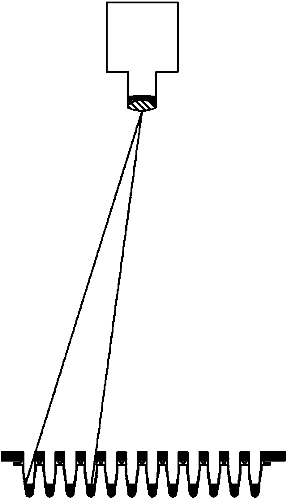
[0004] In order to overcome the deficiencies of the above-mentioned prior art, the present invention proposes an optical system of a multi-channel fluorescent quantitative PCR instrument, which has a high spectral utilization rate, and can overcome the problem of large light intensity differences between wells without adding internal reference fluorescent substances for internal reference correction

Method used


Image

  • Optical system of multichannel fluorescent quantitative PCR instrument
  • Optical system of multichannel fluorescent quantitative PCR instrument
  • Optical system of multichannel fluorescent quantitative PCR instrument

Examples


Embodiment Construction

[0040] The principles and features of the present invention are described below in conjunction with the accompanying drawings, and the examples given are only used to explain the present invention, and are not intended to limit the scope of the present invention.

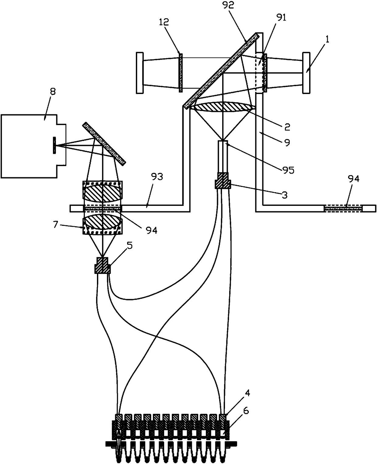
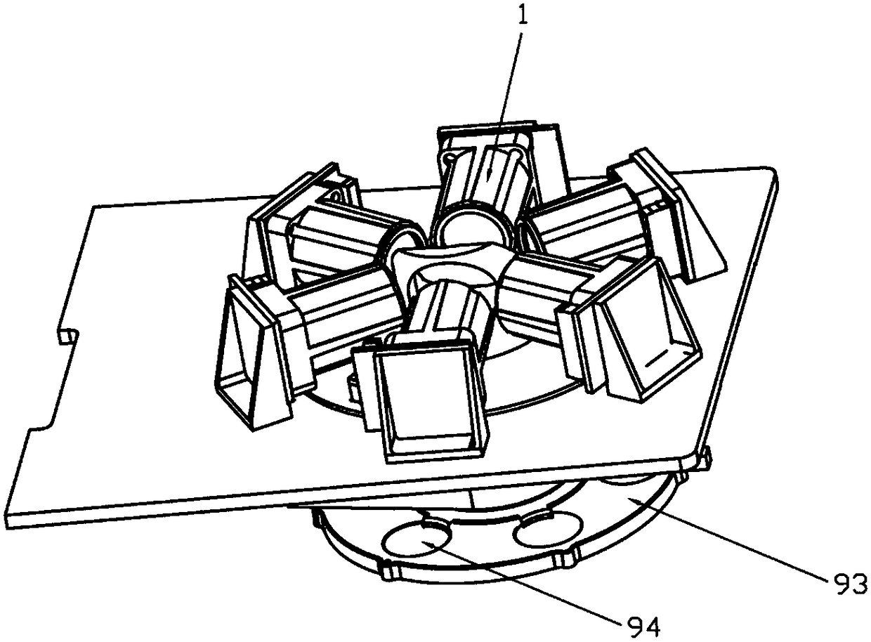
[0041] Such as figure 2 As shown, an optical system of a multi-channel fluorescent quantitative PCR instrument includes multiple switchable LED light sources 1, a convex lens 2, an optical fiber light input end 3, an optical fiber scanning end 4, an optical fiber light output end 5, and a scanning lens array 6. Lens group 7 and imaging sensor 8 . The lens group 7 includes two double-cemented achromat lenses arranged opposite to each other, which can avoid image blur caused by chromatic aberration when different detection channels are used.

[0042]Each LED light source 1 is used to emit excitation light of different wavelengths, and one LED light source 1 provides one channel of excitation light; the convex lens 2...


PUM


Abstract

The invention relates to an optical system of a multichannel fluorescent quantitative PCR instrument. A plurality of optical fiber scanning ends are arranged on a plurality of scanning lenses respectively; each optical fiber scanning end is provided with two transmission optical fibers, each optical fiber scanning end is connected with an optical fiber light inlet end through one of the transmission optical fibers, and each optical fiber scanning end is connected with an optical fiber light outlet end through the other transmission optical fiber; the exciting light emitted by an LED light source enters the optical fiber light inlet end after being condensed by a convex lens, the exciting light enters each transmission optical fiber respectively through the optical fiber light inlet end, then is transmitted to each optical fiber scanning end and exits from each scanning lens, the emission light emitted by a sample after being irradiated by the exciting light is converged to each opticalfiber scanning end through the scanning lens, enters each transmission optical fiber scanning end respectively and then is transmitted to the optical fiber light outlet end, and the emission light exits from the optical fiber light outlet end and enters an imaging sensor through a lens assembly. The technical scheme can improve the spectral utilization rate of a light source, and can overcome theproblem of large light intensity difference between holes without adding internal reference fluorescent substances for internal reference correction.

Description

technical field [0001] The invention relates to the technical field of biological detection, in particular to an optical system of a multi-channel fluorescent quantitative PCR instrument. Background technique [0002] Real-time fluorescent quantitative PCR instrument (QPCR instrument) is the mainstream tool in life science research at present, and has been widely used in pathogen detection, genetically modified food detection, drug efficacy research and gene mutation analysis, etc. Compared with traditional PCR, real-time fluorescence quantitative PCR adds an optical excitation and detection system. The emitted light signal of the DNA fragment increases accordingly during the amplification process, and the content of the original sample can be calculated by detecting the intensity of the emitted light signal during the amplification process. [0003] The optical system of QPCR products currently on the market generally includes an excitation light source, an excitation opti...

Claims


Application Information

Patent Timeline
IPC IPC(8): G01N21/01G01N21/64
CPCG01N21/01G01N21/64G01N2021/0112G01N2201/0833G01N2201/0631G01N2201/062G01N2201/0668G01N2201/068G01N2201/0407G01N2201/0446Y02A50/30
Inventor 张哲夫
Owner 张哲夫
Why Eureka
Eureka Blog
Learn More