
Sewage treatment plant carbon emission quantum chemical calculation method

A technology for sewage treatment plants and carbon emissions, applied in calculation, chemical statistics, electrical digital data processing, etc., can solve problems such as inaccurate calculation methods of carbon emissions

Inactive Publication Date: 2018-06-19
XIAN UNIV OF TECH
View PDF2 Cites 16 Cited by
  • Summary
  • Abstract
  • Description
  • Claims
  • Application Information

AI Technical Summary

Problems solved by technology

[0029] The purpose of the present invention is to provide a quantitative calculation method of carbon emissions in sewage treatment plants, which solves the problem that the calculation method of carbon emissions in sewage treatment plants is not accurate and is applicable to a single sewage treatment plant

Method used


Image

  • Sewage treatment plant carbon emission quantum chemical calculation method
  • Sewage treatment plant carbon emission quantum chemical calculation method
  • Sewage treatment plant carbon emission quantum chemical calculation method

Examples


Embodiment 1

[0173] A sewage treatment plant in Xi'an City was selected. The sewage treatment plant adopts the inverted A2 / O process, and the effluent water quality implements the national first-class standard A standard. The current daily water treatment volume is about 460,000 m 3 / d, the daily sludge production is about 60.58t (dry weight), and all the sludge is transported to landfill after dehydration. The plant's annual water inflow and outflow data, water quality data, power consumption and chemical consumption data are shown in Table 1 below:

[0174] Table 1 Treatment parameters of a sewage treatment plant in Xi'an

[0175]

[0176]

[0177] Parameters such as water quality and operation of this sewage treatment plant, according to the method of the present invention, calculate this sewage plant's annual carbon discharge, following table 2:

[0178] Table 2 Calculation results of carbon emission quantification of a sewage treatment plant in Xi'an

[0179]

[0180] It c...

Embodiment 2

[0184] Taking a sewage treatment plant in Xianyang City as an example, the sewage treatment plant has a treatment capacity of about 30,000 m 3 / d, the sewage treatment process adopts the A2O process, and it was officially put into operation at the end of 2015. Its treatment process is as figure 2 shown. The monthly average data of the sewage treatment plant in 2016 was selected for calculation. The data input by the carbon emission quantification software of the sewage treatment plant are shown in Table 3 below:

[0185] Table 3 Accounting parameter data of sewage treatment plant

[0186]

[0187]

[0188] According to the calculation results of the present invention, the carbon emission of the sewage treatment plant on a certain day in 2016 is 17746.38kgCO 2 , the carbon emission level is 0.658kgCO 2 / t water, of which the direct emission is 7636.37kgCO 2 , the direct emission coefficient is 0.283kgCO 2 / t; indirect emission is 8426.64kgCO 2 , the indirect emiss...


PUM

PropertyMeasurementUnit
heating valueaaaaaaaaaa

Abstract

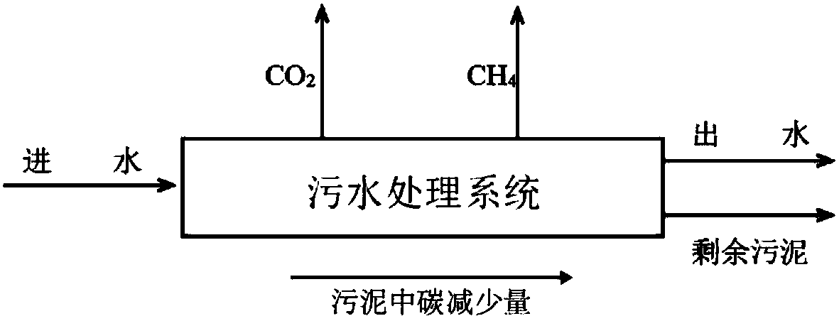
The invention discloses a sewage treatment plant carbon emission quantum chemical calculation method. The sewage treatment plant carbon emission quantum chemical calculation method comprises the stepsof determining the operation time of a sewage treatment plant, working out the sewage treatment plant carbon direct emission EZ, the sewage treatment plant carbon indirect emission EJ, the sewage treatment plant carbon other emission EQ and the sewage treatment plant carbon recycling type emission ER within the operation time separately, and then obtaining a sewage treatment plant carbon emissionquantum chemical calculation result EC. According to the carbon emission quantum chemical calculation method, by delimiting the boundary conditions and calculating period, compared with an existing accounting method, the single sewage treatment plant has the pertinence, powerful data supporting can be provided for sewage treatment plant carbon emission reduction, the obtained carbon emission datais more accurate, and the method is more particularly to a single sewage treatment plant and has the good practical value.

Description

technical field [0001] The invention belongs to the technical field of sewage treatment methods, and in particular relates to a quantitative calculation method for carbon emissions of sewage treatment plants. Background technique [0002] With the continuous increase of global carbon emissions, seeking low-carbon and environmentally friendly development methods has become the development goal of enterprises and even countries. According to the "Global Carbon Project" (Globe Carbon Project) report: global carbon emissions have increased from 2.45 billion tons in 1959 to 9.9 billion tons in 2015, with an average annual growth rate of 131 million tons. The United Nations Intergovernmental Panel on Climate Change (IPCC) pointed out in the climate change report released in 2014 that the continuous increase of carbon emissions has caused climate warming has been confirmed, and the global average temperature has increased by about 0.85°C in the past 100 years, and if the global A ...

Claims


Application Information

Patent Timeline
Patent Type & Authority Applications(China)
IPC IPC(8): G06F19/00
CPCG06F2219/10G16C20/70
Inventor 徐志嫱张程姚宸朕李瑶高扬董雯周爱朝
Owner XIAN UNIV OF TECH
Learn More