Warming equipment of capacitor
A technology for heating equipment and capacitors, applied in the field of capacitors, can solve problems such as unusable capacitors, and achieve the effects of long service life, high hardness and ensuring normal work.
- Summary
- Abstract
- Description
- Claims
- Application Information
AI Technical Summary
Problems solved by technology
Method used
Image
Examples
Embodiment 1
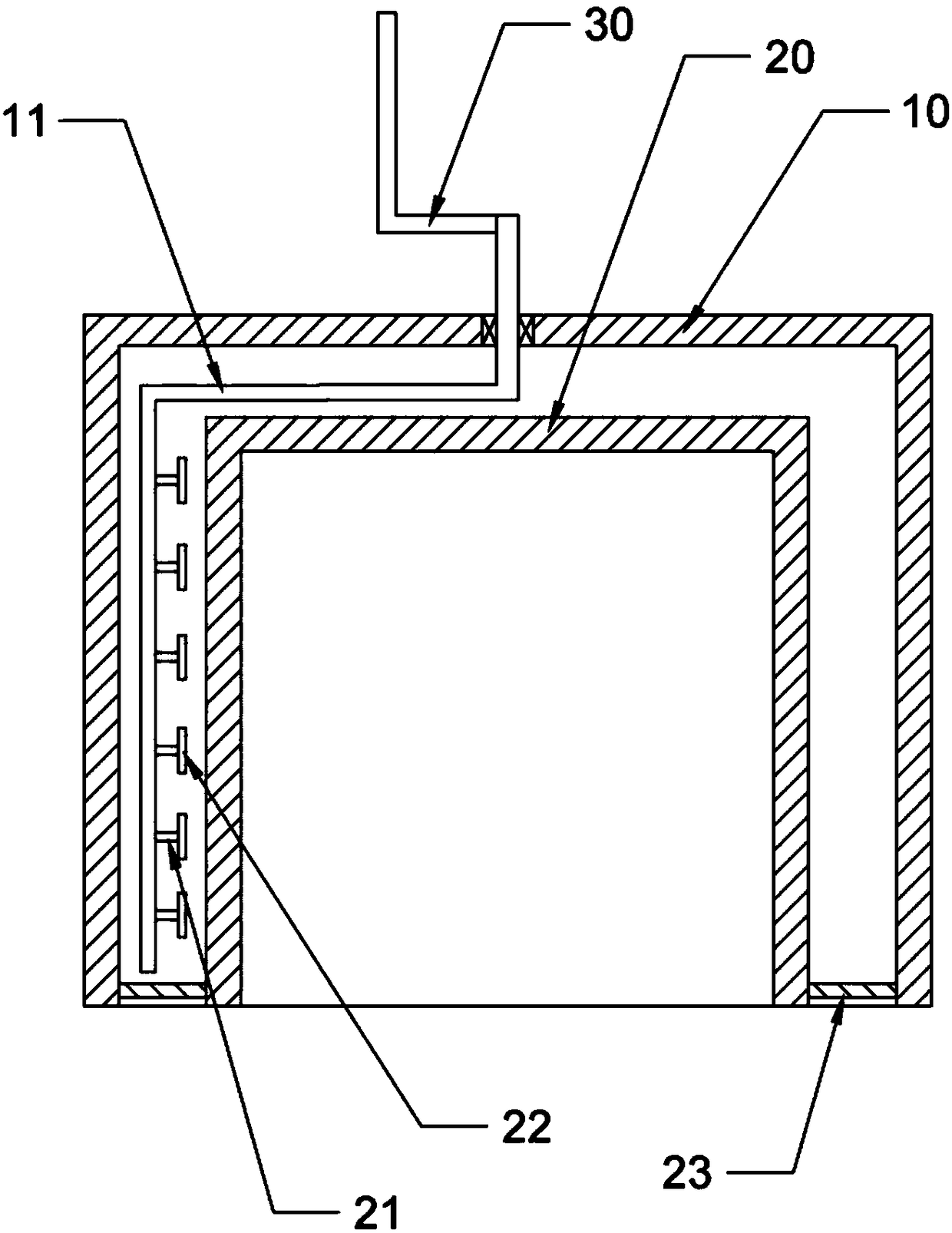
[0033] Basic as attached figure 1 Shown: Thermal equipment for capacitors, including:
[0034] The casing 10 is provided with a mounting hole, a bearing is arranged in the mounting hole, and a sponge water-absorbing layer is arranged on the bearing. Such a design can avoid icing in the bearing, and can also reduce the friction between the mounting hole and the support rod 11 .
[0035] Heat preservation cover 20, heat preservation cover 20 is fixedly installed in the housing 10, an installation cavity is formed between the heat preservation cover 20 and the housing 10, the outer surface of the heat preservation cover 20 is provided with a friction bottom layer, and the interior of the heat preservation cover 20 is provided with a sponge layer. Specifically, the material of the friction bottom layer may be a metal bottom layer, and textures that increase surface roughness are provided on the bottom layer.
[0036] Support rod 11, support rod 11 is positioned at installation c...
Embodiment 2
[0044] Compared with Example 1, the only difference is that a heat conduction hole is provided on the heat preservation cover, and a baffle is provided on one side of the heat conduction hole. The baffle is slidably connected with the heat preservation cover, and the baffle can cover the heat conduction hole. On the other side, there is a thermally conductive rod that expands with heat and contracts with cold, and the support rod is provided with a drain sheet for driving air flow.
[0045] Specific use: when the temperature in the installation cavity is low, the heat conduction rod is in a shrinking state, and the baffle blocks the heat conduction hole. After the temperature in the installation cavity rises, the heat conduction rod expands, the baffle is pushed away by the heat conduction rod, and the heat conduction hole is exposed Come. At this time, the temperature of the air in the installation cavity is also relatively high. After the heat conduction hole is opened, the ...
Embodiment 3
[0047] Compared with Embodiment 1, the only difference is that a magnet capable of forming a closed magnetic field is embedded in the shell, an induction coil is fixed on the support rod, a commutator is provided at the mounting hole, and the commutator is provided with respectively The first brush and the second brush are slidingly connected to the commutator, the first brush is electrically connected to the induction coil, the eddy current coil is embedded in the heat preservation cover, and the eddy current coil is electrically connected to the second brush.
[0048] Specific use: when the support rod rotates, an alternating current will be generated in the induction coil, and then pass through the first brush, the commutator, and the second brush to the eddy current coil, and the eddy current coil is embedded in the heat preservation cover. When there is an alternating current in the eddy current coil, the current in the eddy current coil can be used to heat the heat preser...
PUM
 Abstract
Description
Claims
Application Information
 - R&D
- Intellectual Property
- Life Sciences
- Materials
- Tech Scout
- Unparalleled Data Quality
- Higher Quality Content
- 60% Fewer Hallucinations
Browse by: Latest US Patents, China's latest patents, Technical Efficacy Thesaurus, Application Domain, Technology Topic, Popular Technical Reports.
© 2025 PatSnap. All rights reserved.Legal|Privacy policy|Modern Slavery Act Transparency Statement|Sitemap|About US| Contact US: help@patsnap.com

