
Novel stirrer with cleaning function

A mixer and functional technology, applied in the field of mixers with cleaning function, can solve the problems of high cost, increased power consumption, defective products, etc., and achieve the effects of avoiding deformation, prolonging life, and avoiding mechanical wear.

Inactive Publication Date: 2018-06-26
ZHENGZHOU QISHUO ELECTRONICS TECH CO LTD
View PDF0 Cites 10 Cited by
  • Summary
  • Abstract
  • Description
  • Claims
  • Application Information

AI Technical Summary

Problems solved by technology

[0004] The purpose of the present invention is to solve the phenomenon of residual concrete remaining in the housing and on the mixing device, which may lead to shortened service life of the mixing equipment, increase power consumption, increase cost, and cause defective products. The invention provides a new type of mixer with cleaning function

Method used


Image

  • Novel stirrer with cleaning function

Examples


Embodiment 1

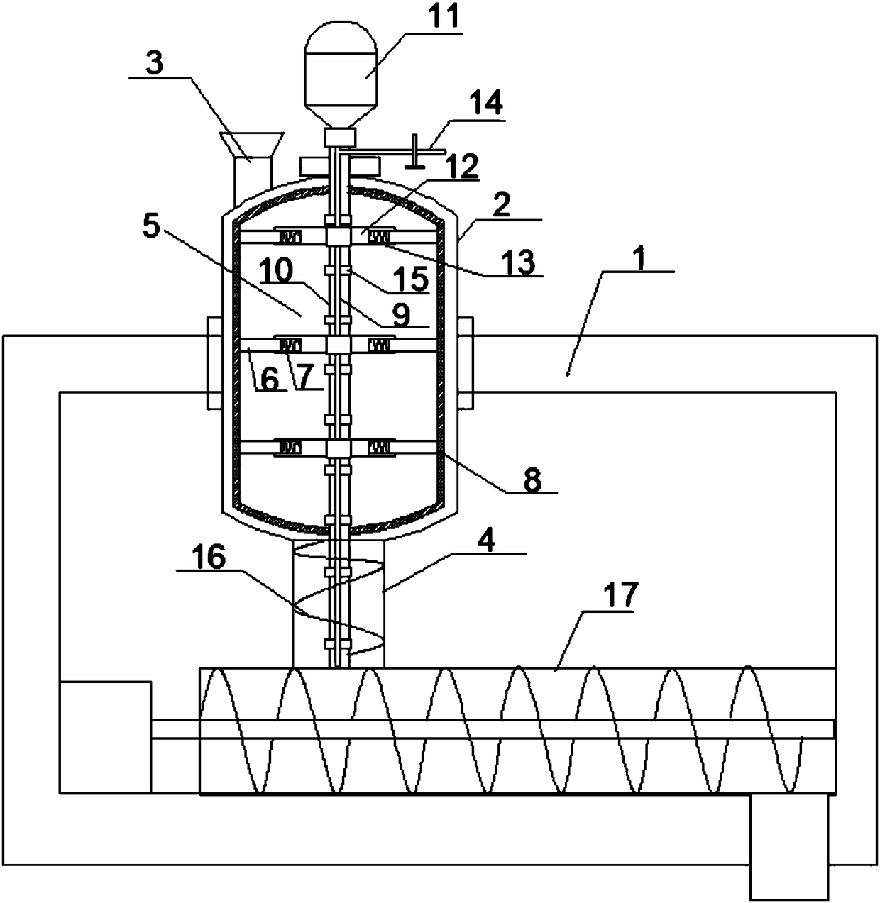
[0021] The technical scheme adopted by the present invention is as follows: a new type of mixer with cleaning function, comprising a bracket 1, a housing 2 fixedly connected to the upper part of the bracket 1, a feed inlet 3 arranged on the top of the housing 2, a 2. The discharge port 4 at the bottom and the stirring device 5 arranged in the housing 2 also include a connecting rod 6, a spring 7 and a scraper 8. The stirring device 5 includes a rotating shaft 10 with a cavity structure 9 for driving The driving device 11 of the rotating shaft 10 and the stirring paddles 12 symmetrically arranged on the rotating shaft 10, the two ends of each of the stirring paddles 12 are respectively provided with connecting grooves 13, and each of the connecting grooves 13 is connected to the connecting rod 6 by the spring 7 The other end of each connecting rod 6 is fixedly connected to the scraper 8, and a water inlet pipe 14 communicating with the cavity structure 9 is provided on the rotat...

Embodiment 2

[0024] On the basis of Embodiment 1, the length of the connecting rod 6 is 1 / 5-1 / 4 of the stirring paddle 12 , and one end of the connecting rod 6 extends to the inside of the connecting groove 13 . This can make the connecting plate and the stirring paddle 12 stably connected.

Embodiment 3

[0026] On the basis of Embodiment 1, the rotating shaft 10 extends to the bottom of the discharge port 4 , and a screw conveying paddle 16 is arranged on the rotating shaft 10 inside the discharge port 4 . By adopting the screw conveying paddle 16, the fully mixed concrete can be automatically conveyed to the outside of the shell 2, which avoids the concrete blocking the discharge port 4. During the cleaning process of the mixer, the screw conveying paddle 16 can accelerate the residue in the discharge port 4 Cleaning of concrete residues inside.


PUM


Abstract

The invention discloses a novel stirrer with a cleaning function. The novel stirrer comprises a support, a casing, a feeding opening, a discharging opening, a stirring device, connecting rods, springsand a scraper, wherein the casing is fixedly connected with the upper part of the support; the feeding opening is formed in the top of the casing; the discharging opening is formed in the bottom of the casing; the stirring device is arranged in the casing; the stirring device comprises a rotating shaft with a hollow structure, a driving device for driving the rotating shaft as well as stirring paddles which are symmetrically arranged on the rotating shaft; connecting slots are respectively formed in two ends of each stirring paddle; each connecting slot is connected with one end of the corresponding connecting rod through the corresponding spring; the other end of each connecting rod is fixedly connected with the scraper; a water inlet pipe communicated with the cavity structure is arranged on the rotating shaft positioned outside the casing; spray nozzles communicated with the cavity structure are uniformly arranged on the rotating shaft, thereby avoiding the problems of mechanical wear, high power consumption and increased cost and prolonging the life of the stirrer.

Description

technical field [0001] The invention belongs to the field of building concrete mixing, in particular to a novel mixer with cleaning function. Background technique [0002] A concrete mixer is a machine that mixes cement, sand and gravel aggregates and water and mixes them into concrete mixtures. It is mainly composed of a stirring shell, a feeding and unloading mechanism, a water supply system, a prime mover, a transmission mechanism, a frame and a supporting device, etc. Concrete mixer is an important part of people's engineering construction process. People need to use concrete mixer to mix concrete during construction. [0003] In the process of mixing and discharging, there are often residual mixing materials left after previous use on the inner wall of the mixing tank and on the mixing blades. These residual materials are very easy to become dry and hard, which not only easily causes mechanical wear and As a result, the service life of the mixing equipment is shortene...

Claims


Application Information

Patent Timeline
IPC IPC(8): B28C5/16B28C5/08B28C7/12B28C7/16B01F15/00B08B9/087B08B9/093
CPCB08B9/0808B08B9/0813B28C5/0806B28C5/0831B28C5/16B28C7/126B28C7/167B01F35/1453B01F35/123
Inventor 高翔
Owner ZHENGZHOU QISHUO ELECTRONICS TECH CO LTD
Learn More