Circular multi-cavity steel plate-concrete composite beam

A technology of concrete and composite beams, applied in bridges, bridge parts, bridge construction, etc., can solve problems such as poor crack resistance, affect project progress, and long construction period, achieve strong lateral restraint, improve construction efficiency, and overcome cracks exposed effect

Inactive Publication Date: 2018-06-26
CHINA UNIV OF PETROLEUM (EAST CHINA)
View PDF0 Cites 0 Cited by
  • Summary
  • Abstract
  • Description
  • Claims
  • Application Information

AI Technical Summary

Problems solved by technology

[0002] At present, urban viaducts, long-span bridges, industrial and civil buildings, etc. are mainly cast-in-place concrete structures. This construction method has a long construction period, which greatly affects the progress of the project. It brings inconvenience to life, causes environmental pollution, and increases social costs
Moreover, the traditional concrete components commonly used in buildings are heavy and unsuitable for long-span structures; at the same time, the crack resistance is poor, and cracks are exposed, which reduces the service life of the components. On-site pouring has many construction procedures, requires maintenance, and the construction period is long and affected by the construction environment. and climatic conditions; traditional concrete components cannot well restrain the lateral sliding of concrete under stress, so that the compressive strength of concrete cannot be fully exerted; in addition, traditional concrete components need formwork support when pouring, and the formed concrete The integrity of the component itself is relatively lacking, and the quality is not easy to control

Method used


Image

  • Circular multi-cavity steel plate-concrete composite beam
  • Circular multi-cavity steel plate-concrete composite beam

Examples


Embodiment Construction

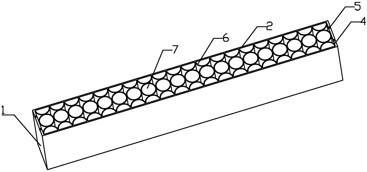
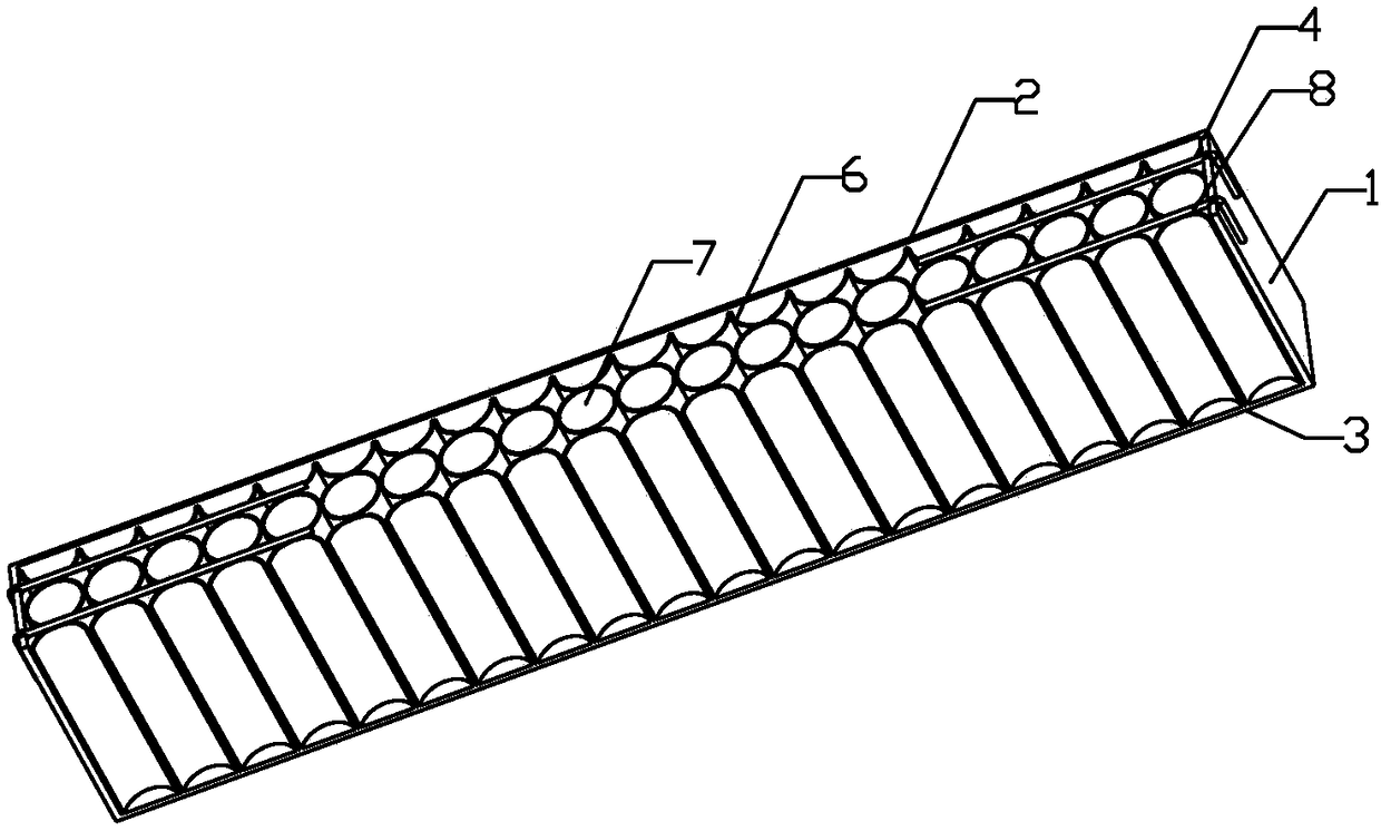
[0011] Such as figure 1 and 2 As shown, a circular multi-cavity steel plate-concrete composite beam includes: a circular multi-cavity space steel beam 1 and concrete, and concrete is poured in the circular multi-cavity space steel beam 1 to form a combined integral member; wherein: The multi-cavity space steel beam 1 is composed of a steel plate shell and a circular or semicircular steel plate cavity 6, and the steel plate shell is composed of 2 long steel plates 2, 1 bottom steel plate 3 and 2 short steel plates 4 to form a structure without a cover. Cuboid structure, circular or semicircular steel plate cavity 6 is welded in the steel plate shell to form a circular multi-cavity steel beam 1, and concrete is poured in the steel beam 1 to form a circular multi-cavity steel plate-concrete composite beam.

[0012] The height of the circular or semicircular steel plate cavity 6 is lower than the steel plate shell, and the height difference between the two must be greater than th...


PUM


Abstract

The invention discloses a circular multi-cavity steel plate-concrete composite beam, and belongs to the field of building engineering. The circular multi-cavity steel plate-concrete composite beam comprises a multi-cavity space steel beam, concrete and a composite integral element which is formed by pouring the concrete into a circular or semicircular multi-cavity space steel beam; and the circular multi-cavity space steel beam is composed of a circular or semicircular steel plate shell and a circular or semicircular steel plate cavity, the steel plate shell is formed by welding five steel plates, the circular or semicircular steel plate cavity is welded in the steel plate shell to form the circular multi-cavity space steel beam, and the circular multi-cavity steel plate-concrete compositebeam is formed by pouring the concrete in the steel beam. The circular multi-cavity steel plate-concrete composite beam has the beneficial effects that the problems that a traditional concrete element is prone to cracking and cracks are exposed are effectively solved, the strong lateral restraining effect from the steel plate cavity on the concrete is achieved, the compressive property of the concrete can be fully achieved, the self-weight is light, the overall property of the composite beam after molding is good, and a steel bar and shape steel in a traditional beam are replaced by the steelplate shell, so that the effect of a formwork is achieved, the construction work of formwork installing and formwork removal is avoided; and the traditional mold can be replaced by the steel plate shell in the construction site, so that the construction progress is speeded up, and economic benefit is increased.

Description

technical field [0001] The invention belongs to the field of construction engineering, and in particular relates to the field of a circular multi-cavity steel plate-concrete composite beam. Background technique [0002] At present, urban viaducts, long-span bridges, industrial and civil buildings, etc. are mainly cast-in-place concrete structures. This construction method has a long construction period, which greatly affects the progress of the project. It brings inconvenience to life, causes environmental pollution, and increases social costs. Moreover, the traditional concrete components commonly used in buildings are heavy and unsuitable for long-span structures; at the same time, the crack resistance is poor, and the cracks are exposed, which reduces the service life of the components. On-site pouring has many construction procedures, requires maintenance, and the construction period is long, and is affected by the construction environment. and climate conditions; tradi...

Claims


Application Information

Patent Timeline
Patent Type & Authority Applications(China)
IPC IPC(8): E04C3/293E01D19/00
CPCE04C3/293E01D19/00
Inventor 李春宝马军李高杰马晓嵩王磊陈玉鹏黄先培
Owner CHINA UNIV OF PETROLEUM (EAST CHINA)
Why Eureka
Try Eureka