
A millimeter-wave high-power radar signal simulator and simulation method

A millimeter-wave radar and signal simulator technology, applied in instruments, radio wave measurement systems, etc., can solve the problems of insufficient frequency band, single channel, low frequency, etc., and achieve the effect of convenient operation, high frequency index and high output power

Active Publication Date: 2020-09-08
BEIJING ZHENXING METROLOGY & TEST INST
View PDF5 Cites 0 Cited by
  • Summary
  • Abstract
  • Description
  • Claims
  • Application Information

AI Technical Summary

Problems solved by technology

At present, the radar signal simulator is mainly based on a single function, or the system is single, or the frequency band is not enough, or the channel is single, and it cannot realize long-distance space radiation. The use environment is limited, and the working high frequency bandwidth of the existing radar simulator is basically in the 2-3GHz, and cannot work in the millimeter-wave frequency range of 32-40GHz. For example, patent application CN201510882404.2 discloses a multi-system radar signal simulator. Although it achieves a wider frequency range, that is, 0.7-18GHz, its The frequency is very low, the maximum is only 18GHz, it cannot be used in the high frequency band range, and its use environment is also greatly restricted, and only long-distance space radiation can be realized

Method used


Image

  • A millimeter-wave high-power radar signal simulator and simulation method
  • A millimeter-wave high-power radar signal simulator and simulation method
  • A millimeter-wave high-power radar signal simulator and simulation method

Examples


Embodiment Construction

[0030] Embodiments of the present invention will be described below with reference to the drawings. Elements and features described in one drawing or one embodiment of the present invention may be combined with elements and features shown in one or more other drawings or embodiments. It should be noted that representation and description of components and processes that are not relevant to the present invention and known to those of ordinary skill in the art are omitted from the drawings and descriptions for the purpose of clarity.

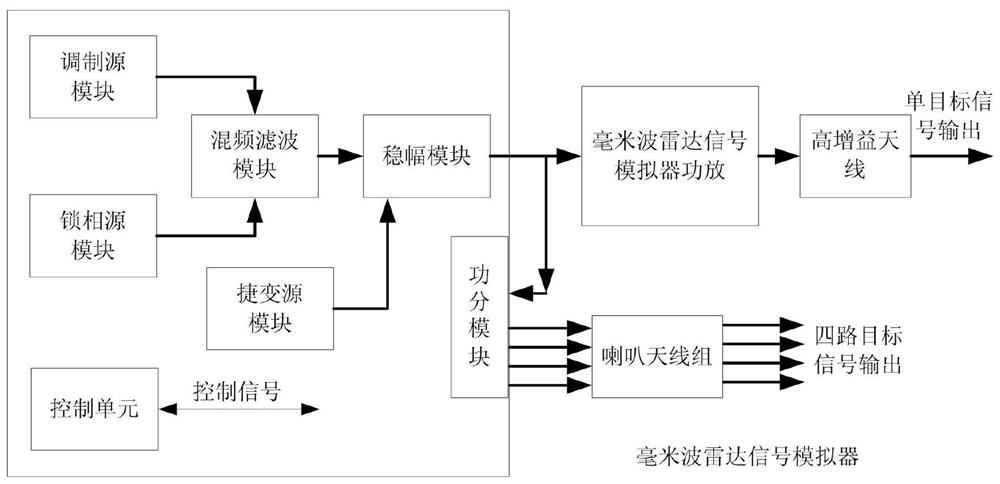
[0031] figure 1 A schematic structural diagram of a millimeter-wave high-power radar signal simulator provided for an embodiment of the present invention; the radar signal simulator includes a millimeter-wave radar signal simulator host, a millimeter-wave radar signal simulator power amplifier, a high-gain antenna, and a horn antenna group.

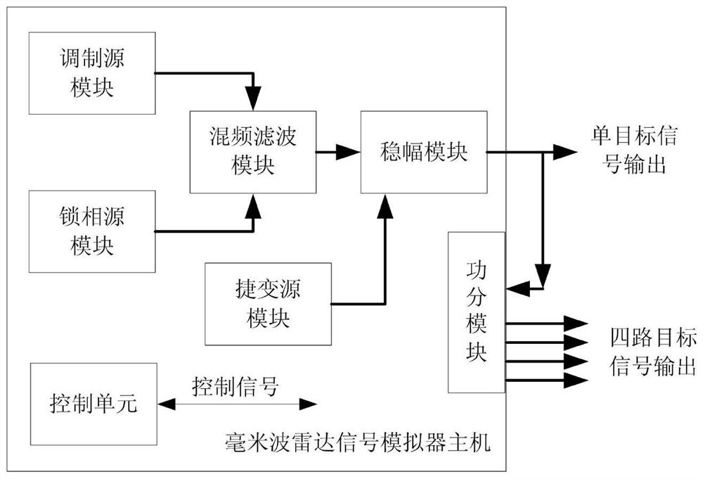
[0032] figure 2 Schematic diagram of the host structure of the millimeter-wave high-power radar signal ...


PUM


Abstract

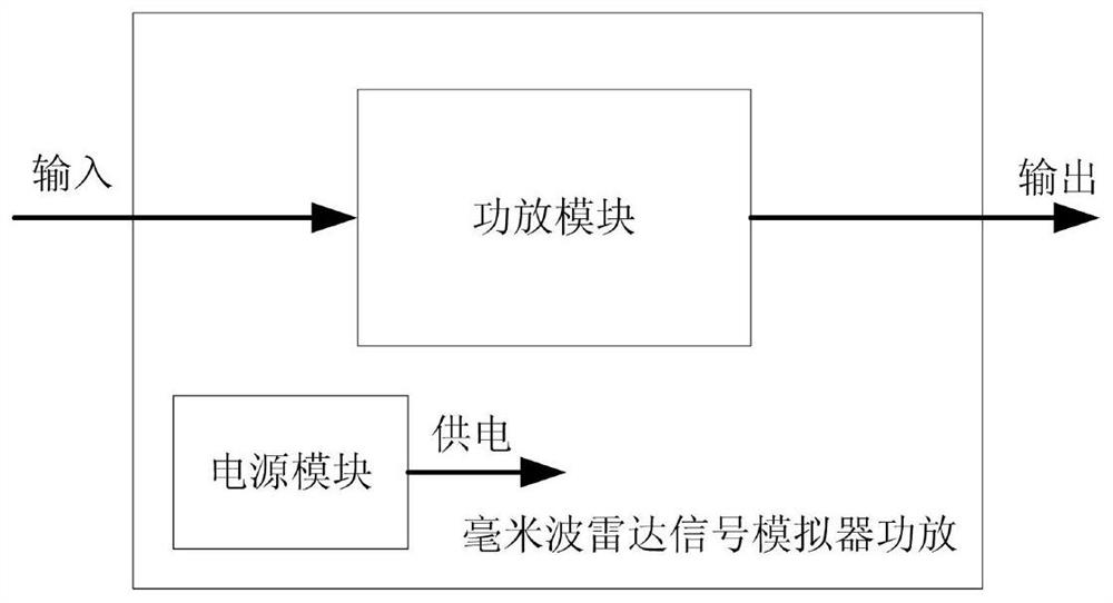
The invention provides a millimeter-wave high-power radar signal simulator and a simulation method. The simulator comprises a millimeter-wave radar signal simulator host, a millimeter-wave radar signal simulator power amplifier, a high-gain antenna and a loudspeaker antenna group; the millimeter-wave radar signal simulator host includes a modulation source module, a locked-phase source module, a mixing and filtering module, an agile source module, an amplitude stabilization module, and a power division module; signals output by the modulation source module and signals outputted by the locked-phase source module are inputted into the mixing and filtering module so as to be subjected to mixing and filtering, and obtain signals and signals outputted by the agile source module pass through theamplitude stabilization module and are divided into two paths of output; one path of the output enters the millimeter-wave radar signal simulator power amplifier so as to be amplified, the amplifiedsignals are converted into single-target output through the high-gain antenna; and the other path of the output enters the power division module and is converted into multi-target output through the loudspeaker antenna group. The simulator of the invention has the advantages of powerful simulation function, wide band (32-40 GHz), large output power (up to 10 W), convenient operation and use, highuniversality, high frequency index and the like, and satisfies the function and performance testing requirements of a millimeter-wave radar warning receiver and also meets the simulation and testing requirements of a millimeter-wave electronic reconnaissance receiver.

Description

technical field [0001] The invention belongs to the technical field of electronic countermeasures, and relates to a radar signal simulator, in particular to a millimeter-wave high-power multi-system radar signal simulator. Background technique [0002] The millimeter-wave high-power radar signal simulator is a laboratory and field test equipment equipped with a radar warning receiver. Technical index test, with long-distance millimeter-wave radar warning receiver test function, is the standard equipment for evaluating important technical indicators of millimeter-wave radar warning receiver. The millimeter-wave radar warning receiver test requires a radar signal simulator that can simulate a variety of millimeter-wave radar transmission signals and the space electromagnetic environment, can simulate radar antenna scanning, and can realize the space radiation of analog signals. At present, the radar signal simulator is mainly based on a single function, or the system is singl...

Claims


Application Information

Patent Timeline
Patent Type & Authority Patents(China)
IPC IPC(8): G01S7/40
CPCG01S7/40G01S7/4052
Inventor 王亚杜金灿杨燕陈自祥郭俊伟薄淑华
Owner BEIJING ZHENXING METROLOGY & TEST INST
Learn More