
Auditory sensitivity detection system based on stimulus frequency otoacoustic emission

A technology of stimulation frequency and otoacoustic emission, which is applied in the fields of audiometer, diagnostic recording/measurement, medical science, etc., can solve the detailed technology and method that does not involve frequency sensitivity quantitative detection, does not involve, does not involve frequency sensitivity quantitative detection, etc. problems, to achieve a wide range of hearing clinical application prospects, the effect of rapid detection

Active Publication Date: 2018-06-29
TSINGHUA UNIV
View PDF7 Cites 12 Cited by
  • Summary
  • Abstract
  • Description
  • Claims
  • Application Information

AI Technical Summary

Problems solved by technology

However, this patent does not involve the detection of stimulus frequency otoacoustic emissions, and the technology and method of using SFOAEs to perform objective quantitative detection of the auditory system's intensity hearing threshold. At the same time, it does not involve the use of SFOAE STCs for quantitative detection of the frequency sensitivity of the auditory system and method; in addition, the patent application number is 201210333260.1, and the title of the invention is "A Stimulus Frequency Otoacoustic Emission Tuning Curve Detection and Calibration System" only discloses the detection method of the stimulation frequency otoacoustic emission tuning curve and the detection technology of the calibration system, but There are no techniques and methods related to the objective and quantitative detection of the intensity hearing threshold of the auditory system using stimulus frequency otoacoustic emissions, nor detailed techniques and methods related to the quantitative detection of frequency sensitivity of the auditory system using SFOAE STCs

Method used


Image

  • Auditory sensitivity detection system based on stimulus frequency otoacoustic emission
  • Auditory sensitivity detection system based on stimulus frequency otoacoustic emission
  • Auditory sensitivity detection system based on stimulus frequency otoacoustic emission

Examples


Embodiment Construction

[0033] The present invention will be described in detail below in conjunction with the accompanying drawings. However, it should be understood that the accompanying drawings are provided only for better understanding of the present invention, and they should not be construed as limiting the present invention.

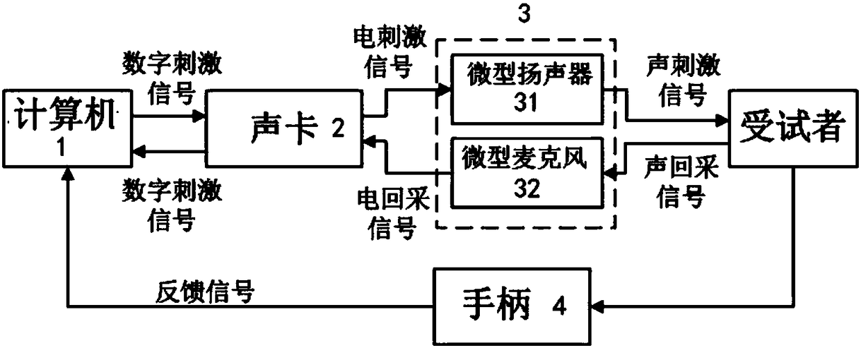
[0034] Such as figure 1 As shown, the auditory sensitivity detection system based on the stimulation frequency otoacoustic emission provided by the present invention is used to obtain the intensity sensitivity and frequency sensitivity of the stimulation frequency otoacoustic emission, including a computer 1, a sound card 2, an acoustic sensor (miniature probe) 3, a front amplifier and signal feedback device; wherein, the acoustic sensor 3 includes a miniature speaker 31 and a miniature microphone 32, in order to isolate the sound in the external auditory canal of the subject from the external sound, the miniature speaker 31 and the miniature microphone 32 can be insert...


PUM


Abstract

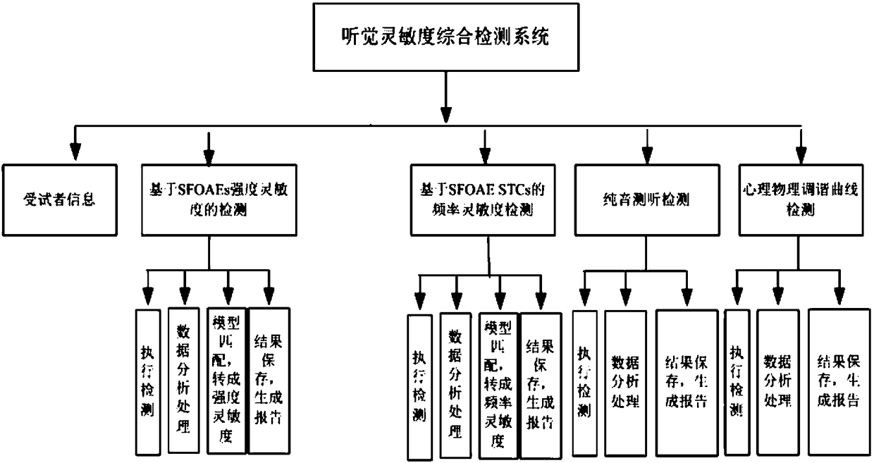
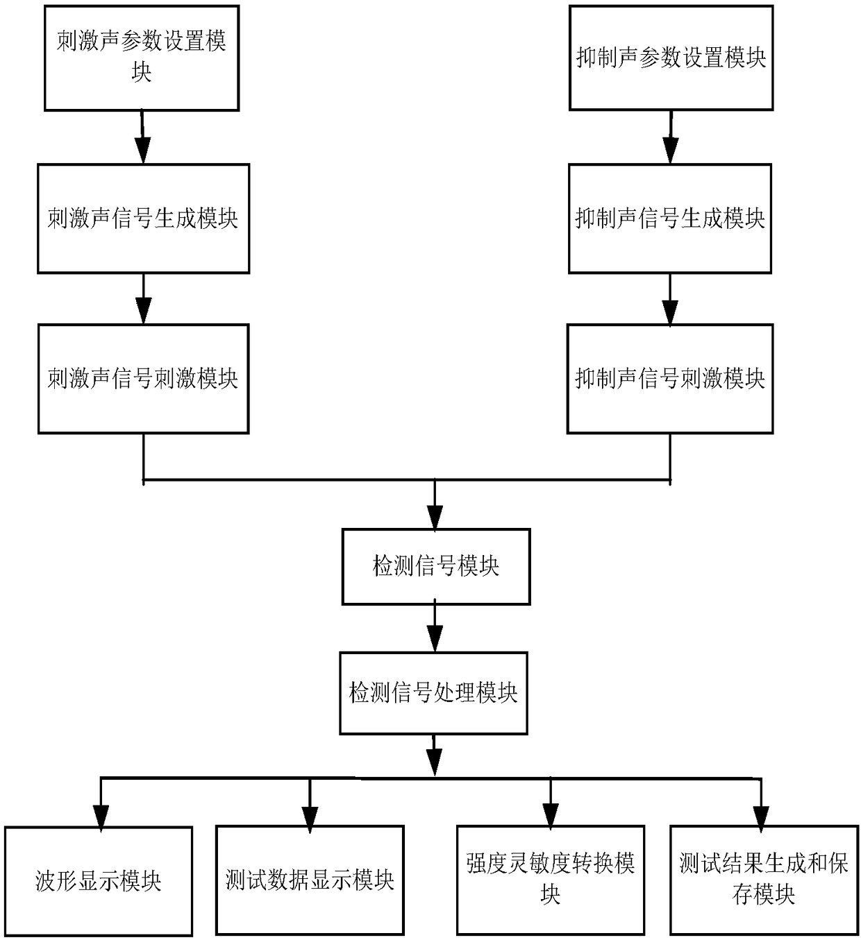
The invention relates to an auditory sensitivity detection system based on stimulus frequency otoacoustic emission. The detection system comprises an audio card, an acoustic sensor, a computer and a signal feedback device; an input end of a micro loudspeaker is connected with the audio card, an output end of a micro microphone is connected with the audio card, and the signal feedback device is connected with the computer; an auditory sensitivity comprehensive detection system is arranged in the computer, a test execution system comprises an intensity sensitivity detection module based on SFOAEs and a frequency sensitivity detection module based on SFOAEs, and the intensity sensitivity detection module based on SFOAEs is used for determining auditory intensity threshold values correspondingto corresponding frequency points by detecting stimulus frequency otoacoustic emission detection data at all the frequency points; the frequency sensitivity detection module based on SFOAEs is used for extracting a stimulus frequency otoacoustic emission inhibition tuning curve at a designated frequency point and determining the frequency sensitivity at the designated frequency point.

Description

technical field [0001] The invention relates to an auditory detection system, in particular to an auditory sensitivity detection system for objectively, quantitatively and comprehensively detecting the intensity sensitivity and frequency sensitivity of the auditory system based on stimulation frequency otoacoustic emission. Background technique [0002] Otoacoustic emissions (OAEs) are weak audio energy produced in the cochlea of ​​the inner ear, transmitted through the ossicular chain and tympanic membrane, and released to the external auditory canal. It is part of the normal function of the human ear. This phenomenon was first discovered by British scholar David Kemp in 1978 and applied clinically. The discovery of otoacoustic emission has confirmed that the cochlea, as a peripheral auditory receptor, can not only passively convert external acoustic signals into bioelectrical signals and send them to the center to cause hearing, but also has an active energy release proces...

Claims


Application Information

Patent Timeline
IPC IPC(8): A61B5/12A61B5/00
CPCA61B5/125A61B5/7203A61B5/7225
Inventor 宫琴
Owner TSINGHUA UNIV
Learn More