Intelligent transverse and longitudinal cloth machine

A distributing machine, horizontal and vertical technology, applied in the field of distributing machines, can solve the problems of low production efficiency and slow feeding speed, and achieve the effects of improving production efficiency, reducing volume and improving feeding speed.

Active Publication Date: 2018-06-29
LUZHOU JIANGXU MACHINERY MFG
View PDF3 Cites 2 Cited by
  • Summary
  • Abstract
  • Description
  • Claims
  • Application Information

AI Technical Summary

Problems solved by technology

[0005] The purpose of the present invention is to provide an intelligent horizontal and vertical material distribution machine in order to solve the problems of slow feeding speed and low production efficiency in the prior art, which can greatly increase the feeding speed by using double-chamber and single-chamber alternate uninterrupted suction ,Increase productivity

Method used


Image

  • Intelligent transverse and longitudinal cloth machine
  • Intelligent transverse and longitudinal cloth machine
  • Intelligent transverse and longitudinal cloth machine

Examples


Embodiment 1

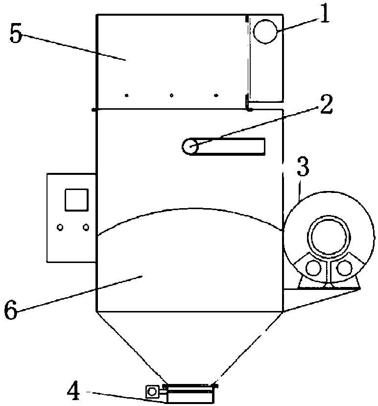
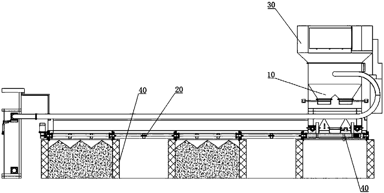
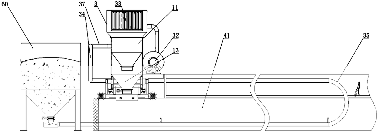
[0052] An intelligent horizontal and vertical material distribution machine, comprising a double-chamber feeder 10, the double-chamber feeder 10 includes a material suction chamber-11, and a material inlet 12 is arranged on the material-suction chamber-11; Material chamber two 13, material suction chamber one 11, and material suction chamber two 13 are connected through discharge hole 14; feeding device.

[0053] In this embodiment, the suction chamber of the prior art is changed from one to two, that is, the first suction chamber 11 and the second suction chamber 13 that are connected to each other, and the second suction chamber 13 is arranged on the first suction chamber 11 Below, that is, the first suction chamber 11 and the second suction chamber 13 are arranged vertically in turn, wherein the first suction chamber 11 is provided with a feed port 12. When working, when starting and running, the discharge device in the discharge port 15 and the discharge hole 14 is in a c...

Embodiment 2

[0055] On the basis of Embodiment 1, a funnel-shaped material guide part 16 is provided at the bottom of the material suction chamber one 11, and the discharge hole 14 is arranged at the bottom of the material guide part 16, and the material guide part 16 communicates with the material suction chamber two 13; The bottom of the second material guide part 13 is provided with a funnel-shaped material guide part two 17, and the discharge port 15 is arranged on the bottom of the second material guide part 17.

[0056]In this embodiment, the first suction chamber 11 communicates with the second suction chamber 13 through the funnel-shaped material guide portion 16 at the bottom of the first suction chamber 11, so after a period of time when the first suction chamber 11 absorbs material, the discharge hole 14 The discharge device in the middle is opened, and the material in the first suction chamber 11 enters the second suction chamber 13 along the material guide part 16 and the disch...

Embodiment 3

[0058] On the basis of Embodiment 2, two material guide parts 16 are provided; three material guide parts 17 are provided.

[0059] In this embodiment, there are two material guide parts 16 . After the pneumatic valve in the discharge hole 17 is opened, the material enters the second material suction chamber 13 along the two funnel-shaped material guides 16 under the action of its own gravity. Compared with only one funnel-shaped material guide part in the material suction room in the prior art, the two material guide parts 16 have obviously improved the transfer speed of the material from the material suction room one 11 to the material suction room two 13, thereby improving the efficiency of this implementation. The processing speed of the example improves the production efficiency. There are 3 guide parts 2 17. After the pneumatic valve in the discharge port 15 is opened, the material is thrown out along 3 funnel-shaped material guide parts 2 17 under the action of its ow...


PUM


Abstract

The invention discloses an intelligent transverse and longitudinal cloth machine, belongs to the field of automatic vinegar brewing equipment and aims to solve the problems of slow feeding speeds andlow production efficiency in the prior art. The machine comprises a double-chamber feeding machine, wherein the double-chamber feeding machine comprises a sucking chamber I; a feeding hole is formed in the sucking chamber I; a sucking chamber II is formed below the sucking chamber I; the sucking chamber I and the sucking chamber II are communicated through discharge holes; outlet holes are formedin the sucking chamber II; discharge devices are arranged in both the outlet holes and the discharge holes. By adopting the machine, material cloth for brewing vinegar can be put into a fermentation tank.

Description

technical field [0001] The invention belongs to automatic vinegar brewing equipment, and in particular relates to a distributing machine. Background technique [0002] The current methods of making vinegar are mainly solid-state vinegar and liquid vinegar. Among them, the flavor of vinegar brewed by solid-state vinegar is better than that of liquid-state vinegar, and in solid-state vinegar, the best flavor is to use The vinegar produced by fermentation in the fermentation tank. In solid-state vinegar making, it is often necessary to put flour, bran, wheat, rice husk and other powder and small particle materials into the fermentation tank. [0003] refer to figure 1 , the existing automatic equipment for brewing vinegar often uses a feeder to perform the feeding operation. The feeder includes a filter chamber 5 at the top, a suction chamber 6 is provided at the bottom of the filter chamber 5, and a high-pressure fan is provided on one side of the suction chamber 6. 3. High ...

Claims


Application Information

Patent Timeline
Patent Type & Authority Applications(China)
IPC IPC(8): C12J1/10
CPCC12J1/10
Inventor 古华贵徐刚
Owner LUZHOU JIANGXU MACHINERY MFG
Why Eureka
Try Eureka