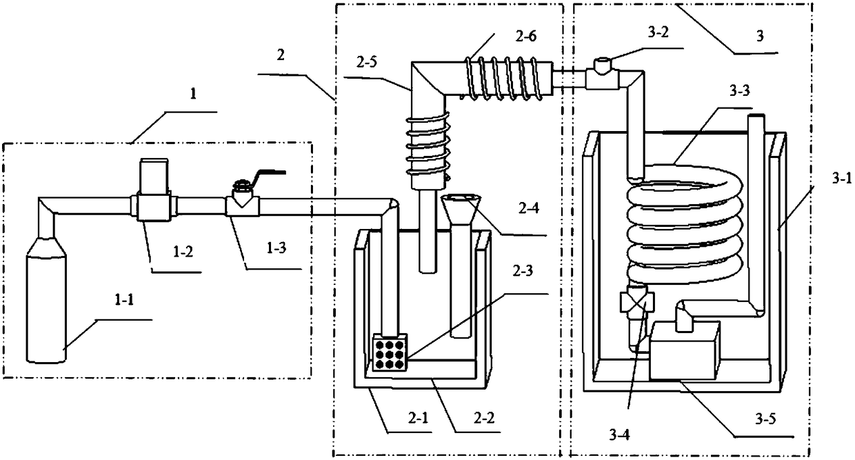
Microscale water vapor generating device and method
A water vapor generation and micro-volume technology, applied in the steam generation method, steam generation, control system, etc., can solve the problem that the amount of water vapor cannot be accurately controlled, and achieve precise controllable carrier gas flow and condensation temperature, continuous and stable supply , the overall structure is simple
- Summary
- Abstract
- Description
- Claims
- Application Information
AI Technical Summary
Problems solved by technology
Method used
Image
Examples
Embodiment 1
[0025] If the user needs the mixed gas flow q=1000mL / min, the temperature t 1 =80°C, where the water vapor concentration c 1 =5%, the carrier gas flow rate should not be higher than 350sccm. Assuming that the cooling effect of the spiral coil is good enough, the outlet carrier gas temperature t 0 and constant temperature water bath temperature t 2 Consistent, outlet carrier gas pressure p 0 = 1 atm.
[0026] Water vapor flow rate in mixed gas: q 1 =q×c 1 =1000×5%=50mL / min;
[0027] Water vapor flow rate under standard state: q 1,0 =q 1 ×273 / (273+t 1 )=50×273 / 353=38.67 sccm.
[0028] Assuming the water bath temperature t 2 =50°C, then the outlet carrier gas temperature t 0 =50°C, according to the thermal properties of saturated water vapor, t can be obtained 0 =50°C,p 0 = Saturated vapor pressure p = 0.012345MPa under the state of 1 atm.
[0029] Water vapor concentration in carrier gas:
[0030] Required standard gas flow rate: q 2 =q 1,0 / c2 -q 1,0 = 38.6...
Embodiment 2
[0033] If the user needs the mixed gas flow q=1000mL / min, the temperature t 1 =80°C, where the water vapor concentration c 1 =5%, the carrier gas flow rate should not be higher than 250sccm. Assuming that the cooling effect of the spiral coil is good enough, the outlet carrier gas temperature t 0 and constant temperature water bath temperature t 2 Consistent, outlet carrier gas pressure p 0 = 1 atm.
[0034] Water vapor flow rate in mixed gas:
[0035] Water vapor flow rate under standard state: q 1,0 =q 1 ×273 / (273+t 1 )=50×273 / 353=38.67 sccm.
[0036] Assuming the water bath temperature t 2 =50°C, then the outlet carrier gas temperature t 0 =50°C, according to the thermal properties of saturated water vapor, t can be obtained 0 =50°C,p 0 = Saturated vapor pressure p = 0.012345MPa in the state of 1 atm.
[0037] Water vapor concentration in carrier gas:
[0038] Required standard gas flow rate: q 2 =q 1,0 / c 2 -q 1,0 = 38.67 / 0.1218-38.67 = 278.82 sccm
[...
Embodiment 3
[0045] If the user needs the mixed gas flow q=1000mL / min, the temperature t 1 =80°C, where the water vapor concentration c 1 =5%, the carrier gas flow rate should not be higher than 350sccm. Assuming that the cooling effect of the spiral coil is average, the outlet carrier gas temperature t 0 higher than the constant temperature water bath temperature t 1 , outlet pressure p 0 = 1 atm. Assuming that the temperature of the water bath is 50°C and the outlet carrier gas temperature is 55°C, the water vapor carryover is different from Example 1, and the water vapor carryover can be controlled by adjusting the flow rate of the carrier gas and the outlet carrier gas temperature respectively.
[0046] a) Adjust the carrier gas flow plan
[0047] Water vapor flow rate in mixed gas: q 1 =q×c 1 =1000×5%=50mL / min;
[0048] Water vapor flow rate under standard state: q 1,0 =q 1 ×273 / (273+t 1 )=50×273 / 353=38.67 sccm.
[0049] According to the thermodynamic properties of saturat...
PUM
 Abstract
Description
Claims
Application Information
 - R&D
- Intellectual Property
- Life Sciences
- Materials
- Tech Scout
- Unparalleled Data Quality
- Higher Quality Content
- 60% Fewer Hallucinations
Browse by: Latest US Patents, China's latest patents, Technical Efficacy Thesaurus, Application Domain, Technology Topic, Popular Technical Reports.
© 2025 PatSnap. All rights reserved.Legal|Privacy policy|Modern Slavery Act Transparency Statement|Sitemap|About US| Contact US: help@patsnap.com

