
Display panel and display device

A display panel and display device technology, which is applied in the direction of instruments, nonlinear optics, optics, etc., can solve the problems of disordered arrangement and light leakage of display devices

Active Publication Date: 2018-06-29
BOE TECH GRP CO LTD +1
View PDF5 Cites 1 Cited by
  • Summary
  • Abstract
  • Description
  • Claims
  • Application Information

AI Technical Summary

Problems solved by technology

[0005] Embodiments of the present invention provide a display panel and a display device to solve the problem that the liquid crystal molecules in the adjacent positions of the reflective area and the transmissive area of ​​a traditional transflective display device affect each other, which easily leads to disordered arrangement and darkening of the display device. prone to light leakage

Method used


Image

  • Display panel and display device
  • Display panel and display device
  • Display panel and display device

Examples


Embodiment Construction

[0016] The technical solutions in the embodiments of the present invention will be clearly and completely described below in conjunction with the accompanying drawings in the embodiments of the present invention. Obviously, the described embodiments are part of the embodiments of the present invention, not all of them. Based on the embodiments of the present invention, all other embodiments obtained by those of ordinary skill in the art without creative work shall fall within the protection scope of the present invention.

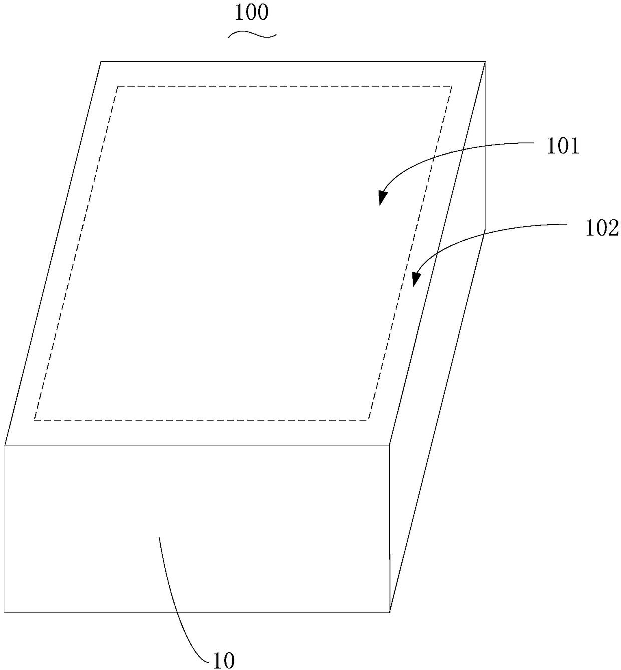
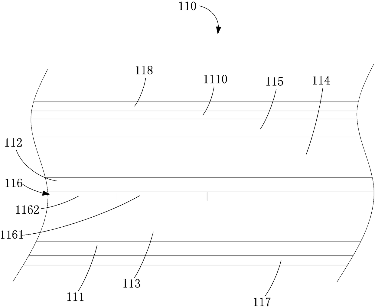
[0017] See also figure 1 with figure 2 , figure 1 Is a perspective view of a display device provided by a preferred embodiment of the present invention, figure 2 for figure 1 A partial cross-sectional view of the display panel shown in. Such as figure 1 with figure 2 As shown in, the display device 100 further includes a display area 101 and a peripheral area 102 surrounding the display area 101. The display area 101 is mainly used to realize the display out...


PUM


Abstract

The invention provides a display panel and a display device. A first liquid crystal layer and a second liquid crystal layer are stacked, a reflective layer including a reflective zone and a photic zone which are adjacently arranged is arranged between the first liquid crystal layer and the second liquid crystal layer, the liquid crystal layers in the same layer are arranged in the same arrangementat the junction of the reflective zone and the photic zone, derangement distribution does not occur, and the occurrence probability of light leak of the display device in a dark state is greatly reduced. In addition, in the reflective zone and the photic zone, the path of ray propagation is the same, the phase difference is the same, the risk of inconsistency between a transmittance curve and a normalized curve in the reflective zone and photic zone is greatly reduced.

Description

Technical field [0001] The present invention relates to the field of display technology, in particular to a display panel and a display device. Background technique [0002] With the advancement of science and technology and the improvement of display technology, liquid crystal display devices (LCD) have increasingly entered people’s lives and work due to their low power consumption, low cost, no radiation and easy operation. It is widely used in various fields, such as homes, public places, offices and personal electronic related products. [0003] According to the source of the light used to display the screen, the display device has a classification of a transmissive display device and a reflective display device. Specifically, the light source of the transmissive display device is a backlight module, and the contrast of the display screen will be reduced outdoors or under strong light; the light source of the reflective display device is an external light source, which has bet...

Claims


Application Information

Patent Timeline
Patent Type & Authority Applications(China)
IPC IPC(8): G02F1/1347G02F1/1335G02F1/13363
CPCG02F1/133528G02F1/133555G02F1/13363G02F1/1347G02F1/133557G02F1/133638G02F2203/09G02F2413/01G02F1/13478G02F1/133553G02F1/13439G02F2201/16
Inventor 古宏刚邵贤杰王春
Owner BOE TECH GRP CO LTD
Learn More