
Air humidity control system and method of proton exchange membrane fuel cell

A proton exchange membrane and fuel cell technology, applied in fuel cells, electrical components, circuits, etc., can solve problems such as only applicable

Inactive Publication Date: 2018-06-29
PINGXIANG HUICHENG PRECISION MACHINERY & ELECTRONICS
View PDF12 Cites 17 Cited by
  • Summary
  • Abstract
  • Description
  • Claims
  • Application Information

AI Technical Summary

Problems solved by technology

At present, the existing fuel cell air humidity control schemes have certain limitations. For example, CN101447575 proposes a fuel cell humidity control method, but it can only adjust the air humidity by adjusting the air introduction rate of the airflow drive device. CN103560261A proposes A control method that controls the output humidity of the dry gas side by adjusting the gas mass flow rate on the wet gas side, but it is only applicable to fuel cells with membrane humidification

Method used


Image

  • Air humidity control system and method of proton exchange membrane fuel cell
  • Air humidity control system and method of proton exchange membrane fuel cell
  • Air humidity control system and method of proton exchange membrane fuel cell

Examples


specific Embodiment 1

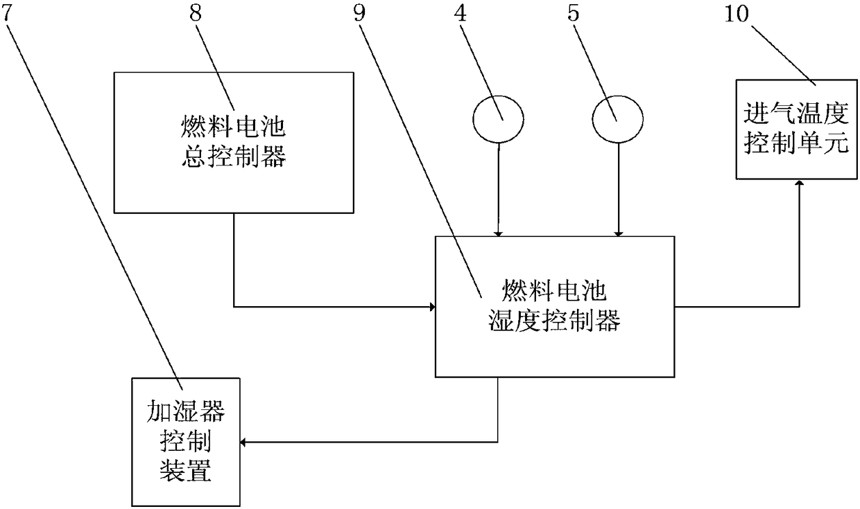
[0062] Such as Figure 5 , the humidification system used in this embodiment includes an air compressor 1 , an intake air temperature control unit 2 , an enthalpy wheel humidifier 3 , a temperature sensor 4 , a humidity sensor 5 and a fuel cell stack 6 .

[0063] The core component of the enthalpy wheel humidifier 3 is a porous ceramic runner, the surface of which is covered with a layer of water-absorbing material. The enthalpy wheel humidifier 3 includes the inlet and outlet of fresh air and the inlet and outlet of hot and humid exhaust gas, and the ceramic runner rotates under the drive of the motor during operation. When the hot and humid exhaust gas of the fuel cell passes through one side of the humidifier, the ceramic runner absorbs the moisture in the exhaust gas and stores it on its surface, and then rotates to the other side of the humidifier; when fresh air enters the enthalpy wheel humidifier 3, it absorbs the porous ceramic surface The water is taken away to comp...

specific Embodiment 2

[0068] Such as Figure 6 , this embodiment includes an air compressor 1 , an intake air temperature control unit 2 , a liquid water jet humidifier 11 , a temperature sensor 4 , a humidity sensor 5 and a fuel cell stack 6 .

[0069] The humidification method adopted by the liquid water jet humidifier 13 is to use high pressure to atomize water through the spray nozzle, spray it into the air flow, and evaporate the water to obtain air with a certain relative humidity. Liquid water jet humidification can control the humidification amount by adjusting the gas flow, water spray pressure, water temperature, etc. In this embodiment, the method of controlling the water spray pressure is used to adjust the relative humidity of the air.

[0070] The fresh air first passes through the air compressor 1, and the airflow after passing through the air compressor 1 needs to be temperature controlled by the intake temperature control unit 2. After passing through the intake temperature control...


PUM


Abstract

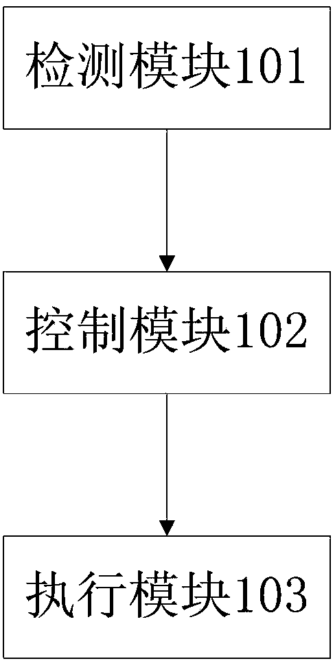
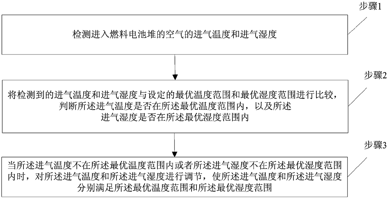
The invention discloses an air humidity control system of a proton exchange membrane fuel cell. The air humidity control system comprises a detection module, a control module and an executing module,wherein the detection module is used for detecting air inlet temperature and air inlet humidity of air entering a fuel cell stack; the control module is used for comparing the detected air inlet temperature and air inlet humidity with pre-set optimal temperature range and optimal humidity range, and sending an adjusting instruction to the executing module when the air inlet temperature is not in the optimal temperature range or the air inlet humidity is not in the optimal humidity range; the executing module is used for adjusting the air inlet temperature and the air inlet humidity according to the adjusting instruction, and enabling the air inlet temperature and the air inlet humidity to meet the optimal temperature range and the optimal humidity range respectively. According to the air humidity control system of the proton exchange membrane fuel cell, the temperature and humidity of the air entering the stack are rapidly adjusted according to the needed optimal temperature and humidity of the fuel cell, so that the inlet air supplied to the fuel cell can meet requirements of a carrying tool under different working conditions and environments.

Description

technical field [0001] The invention relates to the technical field of proton exchange membrane fuel cells for vehicles, in particular to an air humidity control system and method for proton exchange membrane fuel cells. Background technique [0002] A proton exchange membrane fuel cell is a highly efficient power generation device that utilizes the electrochemical reaction between hydrogen and oxides to obtain electricity. At present, my country is vigorously developing new energy electric vehicles. The proton exchange membrane fuel cell has the characteristics of fast start-up speed, wide temperature range, no pollution, and high reliability. It is an ideal power source suitable for the development of new energy electric vehicles. [0003] At present, when fuel cells are used in vehicles such as automobiles, special vehicles, and aerospace vehicles, the output electric power needs to change with the load of the vehicles, so fuel cells not only need to have high power densi...

Claims


Application Information

Patent Timeline
Patent Type & Authority Applications(China)
IPC IPC(8): H01M8/04828H01M8/04701
CPCH01M8/04708H01M8/04835Y02E60/50
Inventor 黄若王腾飞吴定宸陈辉殷鹏张磊
Owner PINGXIANG HUICHENG PRECISION MACHINERY & ELECTRONICS
Learn More