Microstrip slot antenna with reconfigurable directional diagrams

A technology of microstrip slots and directional diagrams, which is applied to the structural connection of antennas, antenna grounding devices, and antenna grounding switches. The effect of increased degrees of freedom

Pending Publication Date: 2018-06-29
SOUTH CHINA NORMAL UNIVERSITY
View PDF0 Cites 11 Cited by
  • Summary
  • Abstract
  • Description
  • Claims
  • Application Information

AI Technical Summary

Problems solved by technology

This often leads to disadvantages such as complicated antenna

Method used


Image

  • Microstrip slot antenna with reconfigurable directional diagrams
  • Microstrip slot antenna with reconfigurable directional diagrams
  • Microstrip slot antenna with reconfigurable directional diagrams

Examples


Embodiment

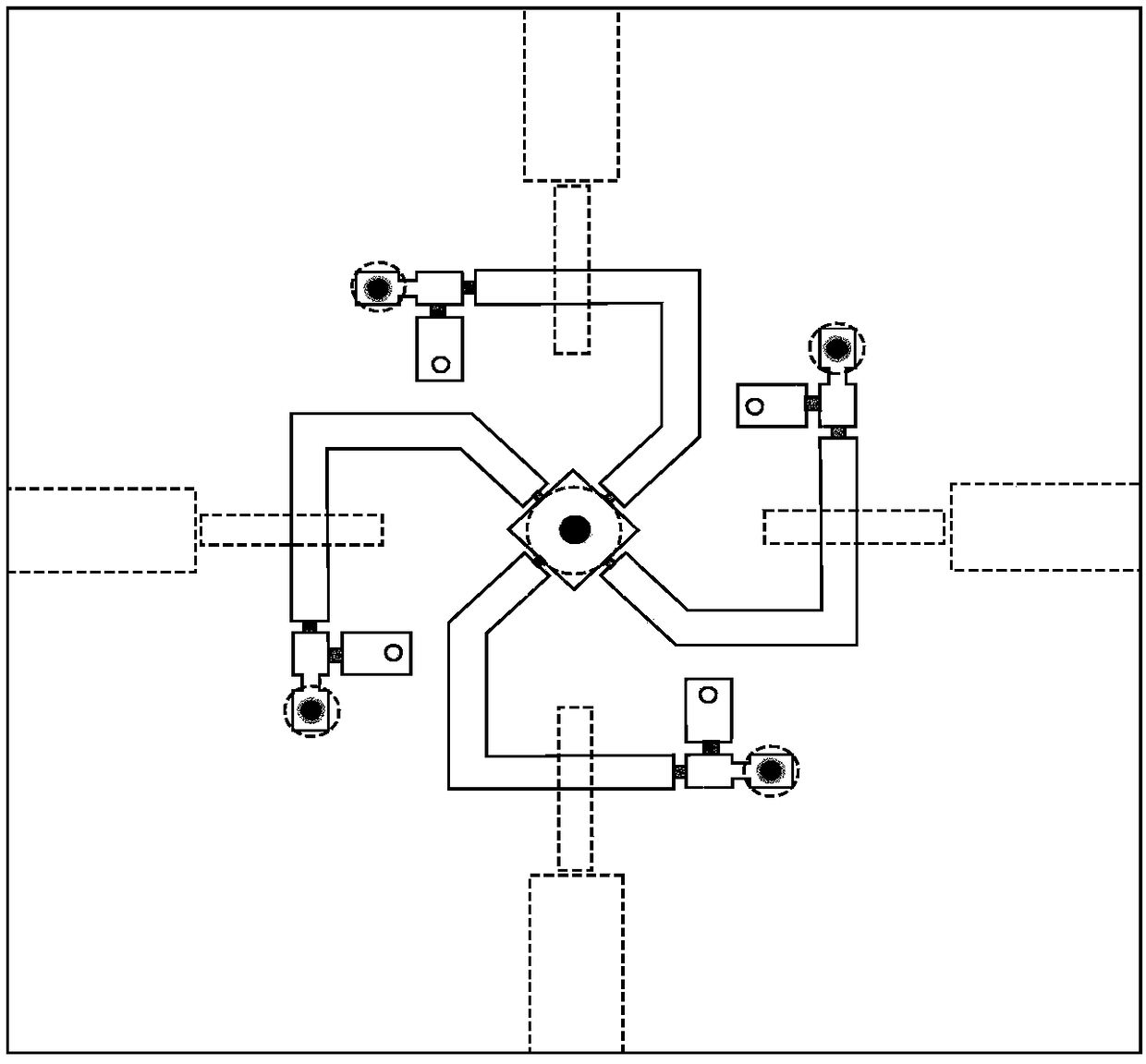
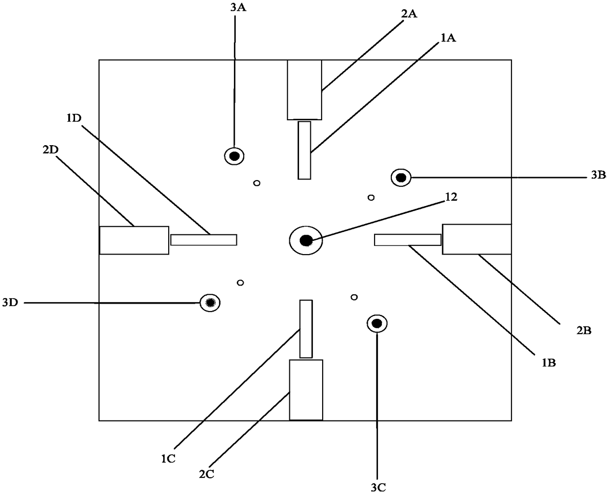
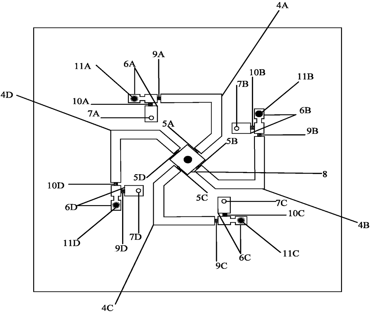
[0036] Such as figure 1 , figure 2 , image 3 with Figure 4 As shown, a microstrip slot antenna with a reconfigurable pattern includes a three-layer structure of a dielectric substrate 13, a feed network 15, and a ground plane 14; the top layer of the dielectric substrate 13 is a feed network 15, and the bottom layer is a The grounding plate 14; the grounding plate 14 includes four rotationally symmetrical and mutually spaced radiation slot units 1A, 1B, 1C, 1D and four rectangular slots 2A, 2B, 2C, 2D arranged at the ends of the radiation slot units; The feeding network 15 includes a square microstrip patch 8 located at the center of the antenna, four switches, four "L" type microstrip coupling branches, and four low-pass filters, and the four "L" type microstrip coupling branches are The microstrip lines 4A, 4B, 4C, and 4D are connected to the four sides of the square microstrip patch 8 through the switches 5A, 5B, 5C, and 5D respectively in the counterclockwise directi...


PUM

PropertyMeasurementUnit
Side lengthaaaaaaaaaa
Widthaaaaaaaaaa
Lengthaaaaaaaaaa

Abstract

The invention discloses a microstrip slot antenna with reconfigurable directional diagrams. The microstrip slot antenna comprises a three-layer structure including a dielectric substrate, a feed network and an earth plate, wherein a top layer of the dielectric substrate is the feed network, and a bottom layer of the dielectric substrate is the earth plate; the earth plate comprises four radiationslot units which are in rotary symmetry and are mutually separated and four rectangular slots formed in the tail ends of the radiation slot units; the feed network comprises a square microstrip patch,a switch, four L-shaped microstrip coupling branches and low-pass filters; the four L-shaped microstrip coupling branches are connected to four sides of the square microstrip patch through switches;one low-pass filter is arranged at the tail end of each L-shaped microstrip coupling branch and is a switch bias circuit; the low-pass filters are used for controlling conduction and disconnection ofthe switches and changing a work mode of an antenna. The microstrip slot antenna disclosed by the invention meets the requirements of small size, compact structure and wider bandwidth and can realizethe reconfigurability of four directional diagrams on the horizontal plane at the same time.

Description

technical field [0001] The invention relates to the technical field of antennas, in particular to a microstrip slot antenna with reconfigurable pattern. Background technique [0002] With the rapid development of science and technology, the transmission of information by means of wireless transmission has become an indispensable means of communication in people's mutual exchanges and cooperation, industrial production, national economic construction and national defense construction. Modern mobile communications and satellite communications play an irreplaceable role in people's lives. Mobile phones, smart watches, and unmanned vending machines use radio waves as information transmission channels and information management products have been widely used. Its position in the national economy and national defense is also becoming more and more important. [0003] As the transmitter and receiver of information in the wireless transmission system, the antenna plays a connecting...

Claims


Application Information

Patent Timeline
IPC IPC(8): H01Q1/38H01Q1/48H01Q1/50H01Q3/24
CPCH01Q1/38H01Q1/48H01Q1/50H01Q3/247
Inventor 李俊龙罗淼辉张祎明刘辉何赛灵
Owner SOUTH CHINA NORMAL UNIVERSITY
Why Eureka
Try Eureka