SS-type electric field coupling wireless power transmission system based on negative resistor

A technology of wireless power transmission and electric field coupling, applied in the direction of electrical components, circuit devices, etc., can solve the problems of reduced transmission efficiency, short transmission distance, low operating frequency, etc., and achieve high efficiency, simple system structure, and stable wireless power transmission Effect

Pending Publication Date: 2018-06-29
SOUTH CHINA UNIV OF TECH
View PDF0 Cites 5 Cited by
  • Summary
  • Abstract
  • Description
  • Claims
  • Application Information

AI Technical Summary

Problems solved by technology

[0004] At present, the traditional space electric field coupling wireless power transmission system mostly uses a bridge inverter composed of IGBT and MOSFET tubes, and cooperates with different soft switching algorithms to realize wireless power transmission, but its operating frequency is low and the transmission distance is short.
Restricted by factors such as power switching tubes and circuit topology, it is still quite difficult to realize high-frequency (above MHz), high-reliability, and high-power switching converters under the existing technical conditions, and the traditional space electric field coupling wireless power transmission The system also has the problem that the transmission efficiency of the system is greatly affected by the transmission distance. Usually, the transmission efficiency decreases greatly with the increase of the distance, which is not conducive to the practical application of the system.

Method used


Image

  • SS-type electric field coupling wireless power transmission system based on negative resistor
  • SS-type electric field coupling wireless power transmission system based on negative resistor
  • SS-type electric field coupling wireless power transmission system based on negative resistor

Examples


Embodiment Construction

[0025] The present invention will be further described below in conjunction with specific examples.

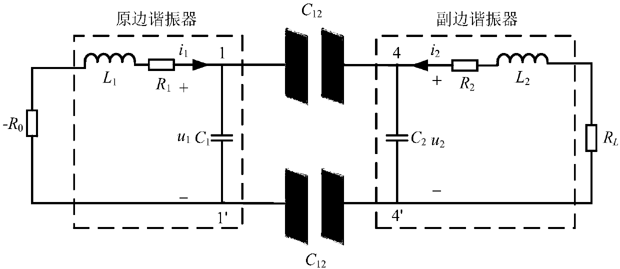
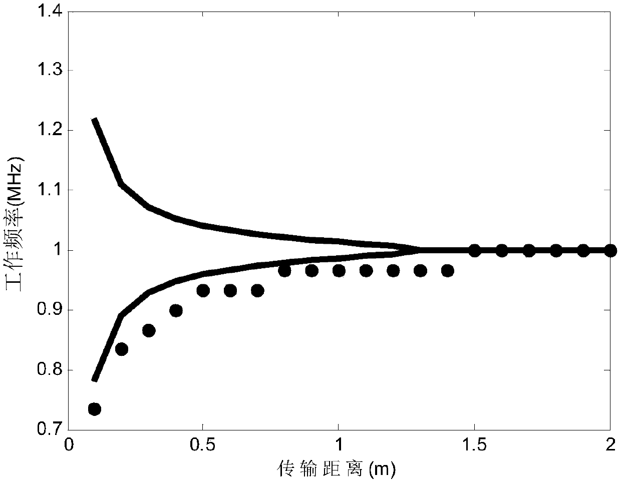
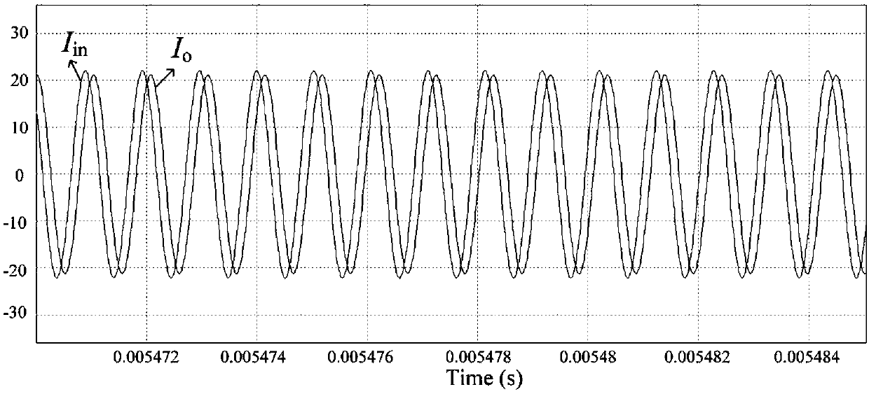
[0026] The basic principle of the SS type electric field coupled wireless power transmission system based on negative resistance provided by the present invention is to use negative resistance to supply power to the system so that the system works at the eigenfrequency. When the transmission distance and load change, the system’s The working frequency will automatically meet the eigenfrequency, achieve a constant high level of transmission efficiency within a certain long transmission distance, while maintaining a constant output power, and realize stable power transmission, which not only solves the problem of the traditional electric field coupling wireless power transmission system The problem that the transmission efficiency drops rapidly with the increase of the distance also maintains a constant power output.

[0027] Such as figure 1 As shown, the SS-type electric fiel...


PUM


Abstract

The invention discloses an SS-type electric field coupling wireless power transmission system based on a negative resistor. The system comprises the negative resistor, a primary side resonator, a secondary side resonator, a coupling capacitor metal electrode plate and a load RL; the primary side resonator comprises a primary side transmitting coil and a primary side resonant capacitor C1 which areconnected in series, and the primary side transmitting coil includes a primary side inductor L1 and a primary side coil internal resistor R1 which are connected in series; the secondary side resonator includes a secondary side receiving coil and a secondary side resonant capacitor C2 which are connected in series, and the secondary side receiving coil includes a secondary side inductor L2 and a secondary side coil internal resistor R2 which are connected in series; the coupling capacitor metal electrode plate is connected to the primary side resonator and the secondary side resonator, the negative resistor is connected to the primary side resonator, and the load RL is connected to the secondary side resonator. According to the system, the structure is simpler, and the working frequency ishigher. When the transmission distance changes, the operating frequency of the system automatically satisfies the eigenfrequency, a constant high-level transmission efficiency can be achieved withina certain long transmission distance, and meanwhile the output power is kept constant.

Description

technical field [0001] The present invention relates to the technical field of wireless power transmission, in particular to an SS type electric field coupling wireless power transmission system based on negative resistance. Background technique [0002] So far, the main transmission method of electric energy is to transmit electric energy through metal wires, usually requiring two or more wires to provide transmission channels for conducting current. The traditional wired power transmission method not only requires a large number of metal wires and complicated wiring projects, but also has to ensure that the insulation between the metal wires is always in good condition. Once a fault such as a short circuit occurs, it will be damaged due to the action of the relay protection device. If the protection device fails, it may cause fire, explosion or electric shock. Moreover, this wired power transmission method also has safety problems such as exposed metal conductors, contact...

Claims


Application Information

Patent Timeline
Patent Type & Authority Applications(China)
IPC IPC(8): H02J50/12
CPCH02J50/12
Inventor 张波疏许健刘功俊
Owner SOUTH CHINA UNIV OF TECH
Why Eureka
Try Eureka