
Dead-beat direct torque control method based on permanent magnet flux linkage sliding mode identification

A technology of direct torque control and permanent magnet flux linkage, which is applied in the control system, control generator, motor control, etc. The effect of improving accuracy

Inactive Publication Date: 2018-06-29
BEIJING SHOUGANG INT ENG TECH
View PDF4 Cites 17 Cited by
  • Summary
  • Abstract
  • Description
  • Claims
  • Application Information

AI Technical Summary

Problems solved by technology

[0004] The purpose of the present invention is to provide a deadbeat direct torque control method based on permanent magnet flux linkage sliding mode identification, which suppresses the problem that the permanent magnet flux linkage parameters have a great influence on the calculation of the reference voltage vector and the system control accuracy is low

Method used


Image

  • Dead-beat direct torque control method based on permanent magnet flux linkage sliding mode identification
  • Dead-beat direct torque control method based on permanent magnet flux linkage sliding mode identification
  • Dead-beat direct torque control method based on permanent magnet flux linkage sliding mode identification

Examples


Embodiment 1

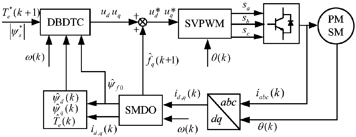
[0026] refer to figure 1 The schematic diagram of the deadbeat direct torque control system based on the permanent magnet flux linkage sliding mode identification of the present invention is shown, and the specific steps include:

[0027] Step 1: The encoder obtains the current speed and rotor position angle of the PMSM, and the Hall element detects the phase current of the PMSM, and transforms the current in the three-phase stationary coordinate system into the current in the two-phase rotating coordinate system through Clark and Park dq axis current.

[0028] Step 2. Substitute the obtained motor speed, position angle, and dq axis current into SMDO, and observe the voltage error caused by the flux linkage disturbance of the permanent magnet.

[0029] Among them, according to the PMSM mathematical model, and considering the disturbance of the motor parameters, the q-axis voltage equation can be obtained as follows:

[0030]

[0031] In the formula, L is the stator induct...


PUM


Abstract

The invention relates to a dead-beat direct torque control method based on permanent magnet flux linkage sliding mode identification and belongs to the technical field of control of permanent magnet synchronous motors. The dead-beat direct torque control method comprises the following steps: substituting obtained motor rotating speed, a position angle and dq axis current into a sliding mode disturbance observer and observing a voltage error; compensating a control system by utilizing an observed value and identifying permanent magnet flux linkage; calculating electromagnetic torque and statorflux linkage of a permanent magnet synchronous motor according to an identification value as feedback values of the control system; substituting reference electromagnetic torque, reference stator fluxlinkage, the feedback electromagnetic torque, the feedback stator flux linkage, the dq axis current, the motor rotating speed and motor parameters into a reference voltage vector calculation formula,adding a calculation result and a compensation value to obtain a compensated reference voltage vector; modulating a corresponding switching signal to act on an inverter. The dead-beat direct torque control method provided by the invention has the advantages that the influence of permanent magnet flux linkage parameters on the calculation of the reference voltage vector is reduced, and the systemcontrol accuracy is improved.

Description

technical field [0001] The invention belongs to the technical field of permanent magnet synchronous motor control, in particular to a deadbeat direct torque control method based on permanent magnet flux linkage sliding mode identification. Background technique [0002] The commonly used control methods of permanent magnet synchronous motor (PMSM) are vector control and direct torque control. The two control methods are simple in structure and easy to implement. However, the dynamic performance and anti-disturbance performance of vector control are poor, and the torque ripple of direct torque control is relatively large. In high-performance control occasions such as aerospace and military equipment, the above two methods can no longer meet the control requirements, so high-performance control methods have become a research hotspot. Among them, deadbeat direct torque control (DBDTC) uses the mathematical model of PMSM to predict the voltage vector acting on the motor at the n...

Claims


Application Information

Patent Timeline
IPC IPC(8): H02P21/13H02P21/14H02P25/022
CPCH02P21/13H02P21/14H02P25/024H02P2207/05
Inventor 侯本帅王淑琴张晓光李洪波孙靖宇苏峰峰张亚超
Owner BEIJING SHOUGANG INT ENG TECH
Learn More