Swirling afterburner chamber based on outer concave cavity

A technology of afterburner and concave cavity, applied in the direction of combustion chamber, continuous combustion chamber, combustion method, etc., can solve the problems of difficult flame propagation and low combustion efficiency, reduce the difficulty of cooling, reduce severe requirements, widen The effect of the flameout limit

Active Publication Date: 2018-07-06
NANJING UNIV OF AERONAUTICS & ASTRONAUTICS +1
View PDF6 Cites 4 Cited by
  • Summary
  • Abstract
  • Description
  • Claims
  • Application Information

AI Technical Summary

Problems solved by technology

[0005] Purpose of the invention: the present invention proposes an afterburner, the combustion chamber realizes the stability and rapid propagation of the flame through the cooperation between the flame stabilizer in the outer concave cavity, the swirl device, and the truncated cone, and solves the difficulty of flame propa

Method used


Image

  • Swirling afterburner chamber based on outer concave cavity
  • Swirling afterburner chamber based on outer concave cavity
  • Swirling afterburner chamber based on outer concave cavity

Examples


Example Embodiment

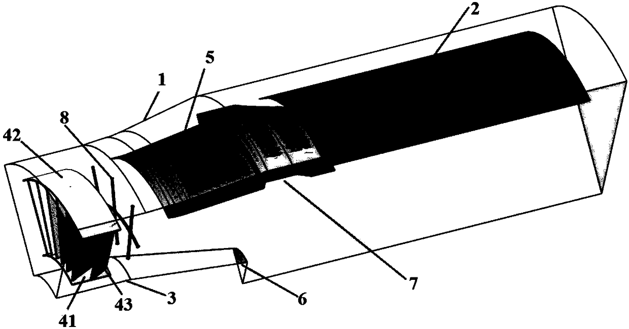
[0026] Example 1: Such as figure 1 with figure 2 As shown, an afterburner includes an outer cylinder assembly, a center body assembly, and an oil circuit assembly; the outer cylinder assembly includes an outer casing 1 and a shock-proof heat shield 2; the center body assembly includes an inner casing 3 , Swirl device 4, splitter plate 5, truncated cone 6, outer cavity flame stabilizer 7; the swirl device includes an inner ring 41, an outer ring 42 and a number of blades 43 connecting the inner ring and the outer ring, the blades are equidistant Arranged, the angle between the blade and the longitudinal section of the swirling device is 25°. The distance between the outer ring and the outer casing is 25% of the inlet diameter of the combustion chamber; the distance between the inner ring and the inner casing of the swirling device is 10% of the inlet diameter of the combustion chamber. The outer cavity flame stabilizer 7 is located at the rear end of the manifold 5, such as im...

Example Embodiment

[0034] Example 2: Using the commercial computational fluid dynamics software Fluent, the numerical simulation of the outer cavity-based swirling afterburner described in Example 1 was carried out, and the relative position between the outer cavity flame stabilizer and the truncated cone was analyzed The effect on flow characteristics and flame propagation. The combustion chamber of Example 1 is arranged in Y0Z0. At this time, the front wall of the outer cavity is aligned with the end of the truncated cone axially, and the flame stabilizer of the outer cavity is moved down 20mm in the radial direction to form Y20Z0 Layout, when the outer cavity flame stabilizer moves back 50mm in the axial direction, it forms a Y0Z50 layout.

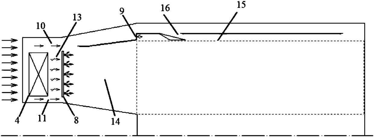
[0035] Figure 4 It is a flow diagram of the cold flow field of the combustion chamber of the present invention. Because the splitter plate is at an angle to the axis of the combustion chamber, the incoming flow deflects toward the cavity when moving along th...


PUM


Abstract

The invention discloses a swirling afterburner chamber based on an outer concave cavity. The swirling afterburner chamber based on the outer concave cavity comprises an outer cylinder assembly, a central body assembly and an oil passage assembly; the outer cylinder assembly comprises an outer cartridge receiver and a shock-proof insulation screen; and the central body assembly comprises a swirlingdevice, an inner cartridge receiver, a frustum, a spreader plate and an outer concave cavity flame stabilizer. Through the cooperation among the outer concave cavity flame stabilizer, the swirling device and the frustum, the stability and rapid propagation of the flame in high speed airflow can be achieved by the relatively low resistance loss, so that the high-efficiency and low resistance combustion is achieved, the effective thermal protection to a hot end part is achieved, the uniform and reasonable distribution of the outlet temperature of the combustion chamber is met.

Description

Technical field [0001] The invention belongs to a combustion chamber of a turbofan engine, and particularly relates to an afterburner. Background technique [0002] With the continuous expansion of flight speed and flight airspace, the performance requirements of engines are increasing day by day. The working conditions of modern high-performance turbofan afterburners have changed greatly compared with the previous combustion chambers. [0003] As the temperature of the inlet gas increases greatly, the ignition in the afterburner becomes easier, and the structural reliability problems of components such as the fuel spray rod and the flame stabilizer become prominent. At the same time, the penetration depth of the fuel that evaporates rapidly at high temperature in the high-speed airflow is very small, and the jet cannot be used to promote the mixing of fuel and air. The ignition source formed in the wake of the stabilizer after ignition is difficult to spread around, so In order t...

Claims


Application Information

Patent Timeline
IPC IPC(8): F23R3/58
CPCF23R3/58
Inventor 范育新缪俊杰翟文辉
Owner NANJING UNIV OF AERONAUTICS & ASTRONAUTICS
Why Eureka
Try Eureka