
Large-slenderness-ratio orbit-control lateral jet-flow force test structure

A large slenderness ratio and orbit control technology, applied in the field of wind tunnel experiments, can solve the problems of reducing the structural design difficulty of other components, the circumferential change of the nozzle layout, and the easy disassembly of the roll angle transformation model, so as to save cost and time, Realize the effect of variable roll angle

Active Publication Date: 2018-07-06
CHINA ACAD OF AEROSPACE AERODYNAMICS
View PDF15 Cites 12 Cited by
  • Summary
  • Abstract
  • Description
  • Claims
  • Application Information

AI Technical Summary

Problems solved by technology

[0006] In the past, for large-slender-ratio aircraft, the forebody attitude control jet interference dynamometer test was mainly carried out. Due to the small flow rate and the form of the air supply pipeline, it is easy to realize, thereby reducing the difficulty of structural design of other components. Orbit-controlled jet flow interference dynamometer test forms an effective means
In addition, in view of the direct force measurement method of jet flow interference, it is necessary to solve the problem of large flow rail-controlled jet flow gas supply, and the integration of model, balance and gas path under the condition that the internal space of the scaled model is severely limited due to the large slenderness ratio design problems, such as the circumferential change of the nozzle layout, the roll angle change and the easy disassembly of the model

Method used


Image

  • Large-slenderness-ratio orbit-control lateral jet-flow force test structure
  • Large-slenderness-ratio orbit-control lateral jet-flow force test structure
  • Large-slenderness-ratio orbit-control lateral jet-flow force test structure

Examples


Embodiment Construction

[0036] The present invention will be described in detail below in conjunction with the accompanying drawings and examples.

[0037] The present invention is used for a large slenderness ratio and large flow rail-controlled lateral jet force measurement test structure, such asfigure 1 As shown, it includes spout block 1, model main body 2, positioning key 3, five-component balance element 4, support system (support system front section 5, support system rear section 6, fixing nut 7, pipe end fixing clamp 8, fixing Transfer rigid air supply pipeline 9, non-metallic hose 10, inner rigid air supply pipeline 11, balance outer lock nut 12, O-ring 13;

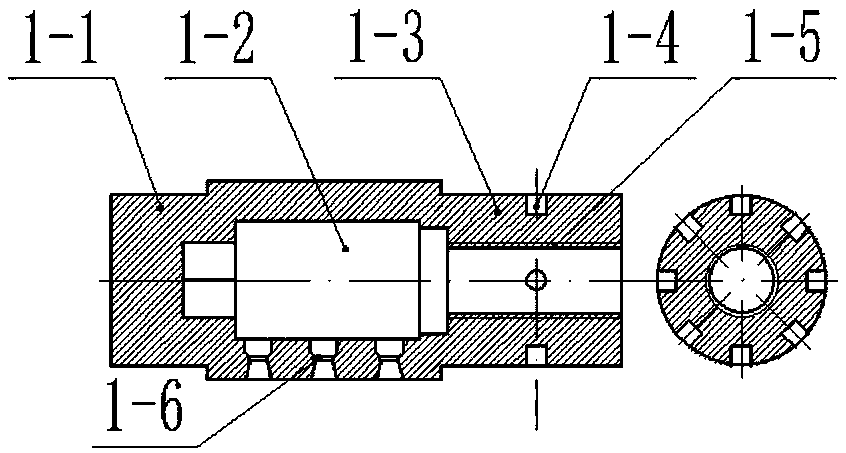
[0038] Such as image 3 As shown, the nozzle block 1 is a columnar structure, including the front-end connection structure 1-1, the resident chamber 1-2, the rear-end connection structure 1-3, the circumferential positioning pin holes 1-4, and the nozzle block gas inlet 1. -5 and nozzles 1-6; the front connection structure is used to...


PUM


Abstract

The invention relates to a large-slenderness-ratio orbit-control lateral jet-flow force test structure comprising a jet pipe block, a main model body, a five-component balance component, an outer balance locking nut, a variable rigidity air-supply pipeline, and a support system. The jet pipe block is used for stabilizing an airflow of an orbit-control lateral jet flow and simulating an orbit-control jet flow. The main model body has a structure with a hollow cavity. The five-component balance component is installed in the hollow cavity of the main model body; one end, approaching the front endof the five-component balance component, of the hollow cavity sleeves the jet pipe block and is fixed; and the rear end of the five-component balance component is supported and fixed by the support system. The five-component balance component and the support system have hollow structures. The variable rigidity air-supply pipeline is installed in the hollow structures; the variable rigidity air-supply pipeline in the hollow structure of the main model body employs a rigid air supply pipeline; one end of the pipeline is connected with a gas inlet of the jet pipe block and the other end is connected with one end of a non-metallic hose; and the other end of the non-metallic hose is connected with the support system fixedly by another rigid air supply pipeline.

Description

technical field [0001] The invention relates to a model design structure used in a sub-transonic wind tunnel with a large slenderness ratio and a large flow rate for orbit-controlled lateral jet interference dynamometric tests, and belongs to the technical field of wind tunnel experiments. Background technique [0002] Reaction Control System (RCS) is a direct force control system that uses small engines to generate reaction force to change the attitude or trajectory of the aircraft. Its function is to supplement the inefficiency of the aerodynamic control surface and quickly change the flight state. The RCS control system has been applied to a variety of super / hypersonic vehicles at home and abroad: American space shuttle, X-37B, Shenzhou spacecraft, gliding reentry vehicles, etc. Especially in air defense and anti-missile weapons, it has been widely used, such as PAC-3, THAAD, Aster and various new low, medium and high altitude interceptors and near space interceptors in o...

Claims


Application Information

Patent Timeline
IPC IPC(8): G01M9/08G01M9/02G01M9/06
CPCG01M9/02G01M9/062G01M9/065G01M9/08
Inventor 罗世杰倪招勇刘耀峰
Owner CHINA ACAD OF AEROSPACE AERODYNAMICS
Learn More