Thermal barrier coating working condition simulation and real-time monitoring device

A technology of working condition simulation and real-time monitoring, applied in the field of aero-engines, can solve problems such as failure to meet actual needs, low integration, harsh multi-field coupling service environment of aero-engines, etc.

Inactive Publication Date: 2018-07-06
XIANGTAN UNIV
View PDF10 Cites 23 Cited by
  • Summary
  • Abstract
  • Description
  • Claims
  • Application Information

AI Technical Summary

Problems solved by technology

[0003] Aeroengines have an extremely harsh multi-field coupling service environment, and the working conditions are extremely complex, requiring a large amount of experimental data to test materials. However, traditional test methods cannot accurately simulate the service environment of aeroengines, which limits the thermal barrier coating in coupling environments. The research on the damage and failure process of the layer cannot meet the actual needs, and requires a variety of monitoring equipment to monitor the simulation process, and the integration level is not high

Method used


Image

  • Thermal barrier coating working condition simulation and real-time monitoring device
  • Thermal barrier coating working condition simulation and real-time monitoring device
  • Thermal barrier coating working condition simulation and real-time monitoring device

Examples


Embodiment Construction

[0023] In order to make the object, technical solution and advantages of the present invention clearer, the present invention will be further described in detail below in combination with specific embodiments and with reference to the accompanying drawings. It should be understood that these descriptions are exemplary only, and are not intended to limit the scope of the present invention. Also, in the following description, descriptions of well-known structures and techniques are omitted to avoid unnecessarily obscuring the concept of the present invention.

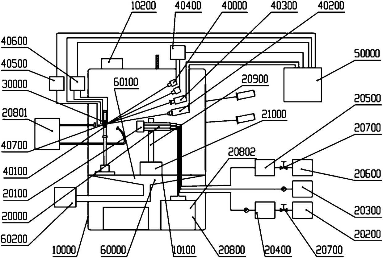
[0024] refer to figure 1, The thermal barrier coating working condition simulation and real-time monitoring device described in this embodiment includes: a box body 10000, a working condition simulation component 20000, a sample clamping component 50000, a monitoring component 60000 and a system control component 70000; a working condition simulation component 20000 Used to simulate the working environment of the sample ...


PUM


Abstract

The invention provides a thermal barrier coating working condition simulation and real-time monitoring device. The device comprises a box, a working condition simulation assembly, a sample clamping assembly, a monitoring assembly and a system control assembly, wherein the working condition simulation assembly is used for simulating the working condition of a sample to be tested; the sample clamping assembly is arranged inside the box; the sampling clamping assembly is used for clamping the sample to be tested; the monitoring assembly is used for collecting and processing test data in the simulation process; a detection assembly is electrically connected with the system control assembly, and the system control assembly is used for controlling the simulation process. Through the arrangementof the working condition simulation assembly, the working condition of an aircraft engine can be simulated, and real-time monitoring is performed on the simulation process by using the monitoring assembly, so that an extreme multi-field coupling environment can be realized, and the complex multi-field coupling service environments, such as high temperature thermal shock, hard particle erosion andhigh temperature corrosion, of the thermal barrier coating material in the real service process can be simulated.

Description

technical field [0001] The invention relates to the field of aero-engines, in particular to a thermal barrier coating working condition simulation and real-time monitoring device. Background technique [0002] Aeroengines are known as the "heart" of aircraft and play a decisive role in the development of the aerospace industry. The key parameter of an engine is its thrust-to-weight ratio. With the increase of the thrust-to-weight ratio, the temperature at the front inlet of the aeroengine turbine has exceeded 1700°C. The substantial increase in the inlet temperature of the turbine undoubtedly puts forward higher requirements on the performance of the superalloy material and thermal protection technology of the hot end parts of the engine. The thermal barrier coating system is a multilayer functional material with high temperature resistance and high heat insulation. It is composed of a top ceramic layer that acts as heat insulation, delays oxidation, and resists erosion / cor...

Claims


Application Information

Patent Timeline
Patent Type & Authority Applications(China)
IPC IPC(8): G01N3/56G01N3/60G01N3/06G01N17/00G01N17/02
CPCG01N3/06G01N3/066G01N3/068G01N3/565G01N3/567G01N3/60G01N17/002G01N17/02G01N2203/0066G01N2203/0226G01N2203/024G01N2203/0617G01N2203/0641G01N2203/0658G01N2203/0682G01N2203/0694
Inventor 杨丽周文峰周益春谭明朱旺李朝阳
Owner XIANGTAN UNIV
Why Eureka
Try Eureka