
Coating cutter steady-state temperature field predicting method considering cutter rear surface abrasion

A prediction method and flank face technology, applied in the field of metal cutting, can solve the problems of rarely considering the temperature distribution of the tool, aggravating the wear of the tool, etc., to achieve practical engineering application significance, improve processing efficiency, and optimize cutting process parameters. Effect

Inactive Publication Date: 2018-07-06
WUHAN UNIV OF TECH
View PDF0 Cites 8 Cited by
  • Summary
  • Abstract
  • Description
  • Claims
  • Application Information

AI Technical Summary

Problems solved by technology

[0003] At the level of theoretical research, the current research on coated tools rarely involves the influence of the tool coating / substrate diffusion layer on cutting heat conduction, and the high temperature generated in the cutting area is considered to be the main reason for the chemical or diffusion reaction between the tool and the workpiece, and then increased tool wear
In addition, the thermal modeling of coated tools is mainly based on sharp tools to establish heat transfer models, but rarely considers the tool temperature distribution under the flank wear state

Method used


Image

  • Coating cutter steady-state temperature field predicting method considering cutter rear surface abrasion
  • Coating cutter steady-state temperature field predicting method considering cutter rear surface abrasion
  • Coating cutter steady-state temperature field predicting method considering cutter rear surface abrasion

Examples


Embodiment Construction

[0024] In order to make the object, technical solution and advantages of the present invention clearer, the present invention will be further described in detail below in conjunction with the accompanying drawings and embodiments. It should be understood that the specific embodiments described here are only used to explain the present invention, not to limit the present invention.

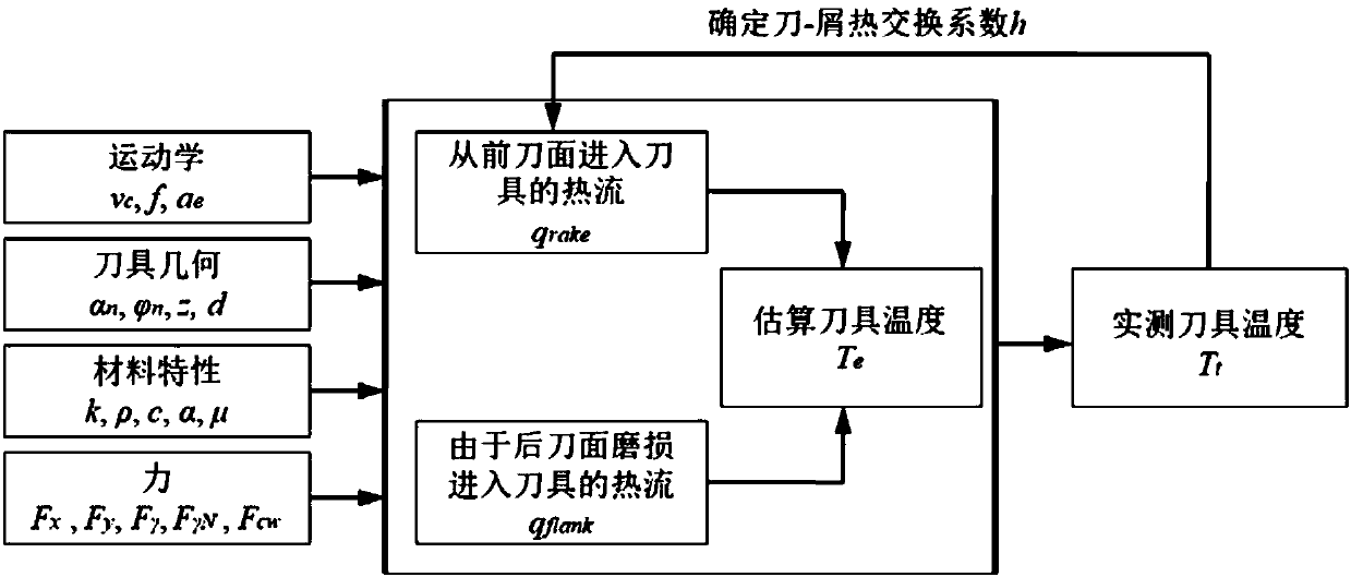
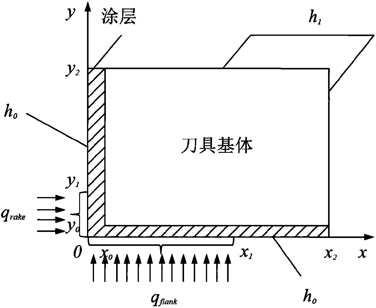
[0025] Such as figure 1 As shown, a method for predicting the steady-state temperature field of a coated tool considering flank wear includes the following steps: (1) Establish a thermal model for describing the temperature change of the coated tool during the cutting process, (2) calculate the previous The heat flux density of the cutter face entering the tool, (3) calculate the heat flux density entering the tool due to the flank wear, (4) evaluate the heat exchange coefficient through the cutting experiment data to determine the heat flow distribution ratio between the chip and the tool, and the...


PUM


Abstract

The invention discloses a coating cutter steady-state temperature field predicting method considering cutter rear surface abrasion. By means of the method, firstly, a thermal model used for describingthe coating cutter temperature change in the cutting and machining process is built, secondly, heat flux entering a cutter from the front cutter surface and heat flux entering the cutter due to abrasion of the rear cutter surface are calculated respectively, through cutting experimental data, heat exchange coefficients are estimated to be used for determining the heat flux distribution proportionfor entering chips and the cutter, and then instantaneous cutter temperature distribution under different cutter states is simulated and predicated. Precise cutter temperature prediction in the abrasion state of a coating cutter is easily achieved, by optimizing technology parameters, the service life of the cutter is prolonged, and the machining surface quality of parts is improved.

Description

technical field [0001] The invention belongs to the technical field of metal cutting, and in particular relates to a method for predicting the steady-state temperature field of a coated tool considering flank wear. Background technique [0002] Coated cutting tools are widely used in the cutting of difficult-to-machine materials such as titanium alloys and high-temperature alloys. For such difficult-to-machine materials, a significant phenomenon in the cutting process is frequent tool wear, which affects processing efficiency and surface quality of parts. In the actual cutting process, due to the lack of on-line monitoring devices and methods for tool wear, engineers and technicians often choose very conservative cutting parameters such as low spindle speed and small depth of cut in order to reduce unforeseen risks, and the optimization of process parameters depends on "passive" operation personnel experience. [0003] At the level of theoretical research, the current rese...

Claims


Application Information

Patent Timeline
Patent Type & Authority Applications(China)
IPC IPC(8): G06F17/50
CPCG06F30/17
Inventor 朱大虎庄可佳
Owner WUHAN UNIV OF TECH
Learn More