Double-conductor equipment wire clamp

A technology of equipment wire clips and double wires, which is applied in the direction of conductive connection, multi-conductor connectors, electrical components, etc., can solve the problems of unfavorable power grid operation, affecting the service life of fittings, and magnifying weld stress, so as to prevent water accumulation in fittings Cracking, preventing excessive temperature rise of fittings, and good stress state

Inactive Publication Date: 2018-07-06
STATE GRID XINJIANG ELECTRIC POWER CO ECONOMIC TECH RES INST +1
View PDF2 Cites 4 Cited by
  • Summary
  • Abstract
  • Description
  • Claims
  • Application Information

AI Technical Summary

Problems solved by technology

[0003] The clamp of traditional double-conductor equipment adopts sleeve welding, and the crimping sleeve is welded on the outside of the double-split cylindrical end. In actual operation, the external force is transmitted from the wire to the crimping tube. It is the sum of the lengths of the non-crimping area and the double-split cylindrical end, the arm of force is longer, the moment increases, the stress actually borne by the weld is amplified, and the risk of weld cracking increases; , the leakage hole can only be drilled after the installation position and direction are determined on site, and the construction is troublesome; because there is a certain gap between the crimping tube of the equipment line clamp and the double-split cylindrical end, the accumulated water in the crimping tube cannot be completely drained through the leaking hole Clean, the accumulated water expands due to freezing in cold weather, causing greater stress inside the fittings, and the welds are prone to bursting, which affects the service life of the fittings
Various defects in the existing technology lead to the cracking and swelling of the welding seam often occur in the actual operation of the double-conductor equipment clamp in the station. The maintenance cost is high and the maintenance is frequent, which is not conducive to the safe operation of the power grid.

Method used


Image

  • Double-conductor equipment wire clamp
  • Double-conductor equipment wire clamp

Examples


Embodiment Construction

[0019] The present invention will be further described in conjunction with the accompanying drawings and embodiments.

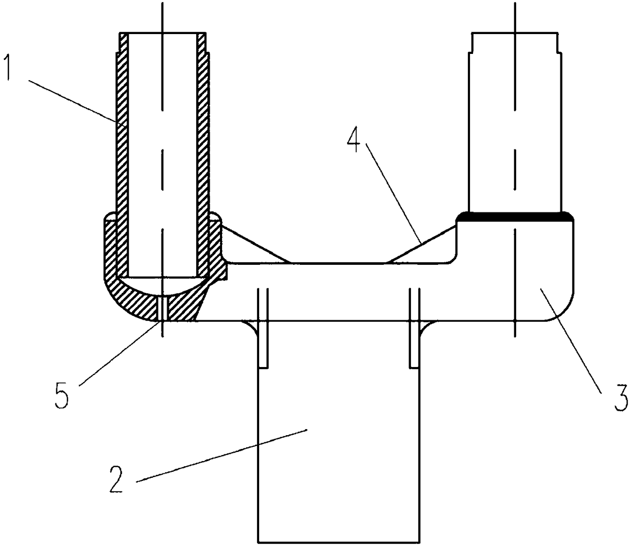
[0020] A wire clip for double-conductor equipment includes a wire clip body and a crimping pipe, and the crimping pipe and the wire clip body are connected in an inserting manner.

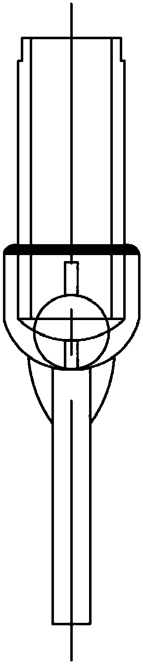
[0021] Such as figure 1 , 2 As shown, a double-conductor equipment clamp includes a clamp body and a crimping tube 1. The equipment clamp body adopts a casting process and is made of aluminum alloy, and its tensile and bending properties are greatly improved; the crimping tube 1 and The clamp body adopts interpolation connection. In this embodiment, the crimping tube 1 and the clamp body adopt interpolation welding. The clamp body includes a terminal board 2 and a "U"-shaped part 3. The " Both ends of the U"-shaped piece 3 are respectively provided with a hollow cylinder for inserting the crimping tube 1, the structure of the inner hollow part of the hollow cylinder is a combina...


PUM


Abstract

The invention discloses a double-conductor equipment wire clamp, which comprises a wire clamp body and a crimping pipe, wherein the crimping pipe and the wire clamp body are connected in an interpolating mode. The invention adopts the crimping pipe interpolation welding, effectively increases the welding area and improves the overall strength of a welding seam. After the welding area is increased,the overall current carrying capacity of the wire clamp is improved, and the problem of excessive temperature rise of fittings caused by insufficient current carrying area is effectively prevented. In actual operation, an external force is transmitted from conductors to the crimping pipe, a distance between a direct force-receiving portion of the crimping pipe and a welding seam fixed point is just a distance in a non-crimping region, the force arm is short, the stress state is good, the wire clamp can prevent welding snap under the action of a higher external force, and long-term operation is guaranteed; the material of the double-conductor equipment wire clamp is changed from pure aluminum in the traditional scheme to aluminum alloy, thus the tensile property and bending resistance aregreatly improved; and water leaking holes can be formed directly under accumulative water positions of the fittings and are directly processed in a fitting production factory, the working procedures on the construction site are reduced, the installation efficiency is improved, and the fittings are effectively prevented from spalling due to the accumulative water.

Description

technical field [0001] The invention relates to the field of AC substation engineering, in particular to a clamp for double-conductor equipment. Background technique [0002] At present, my country has become a power transmission country with the most AC projects in operation and under construction, the largest capacity and the longest lines in the world. The substation is an important part of the power transmission project. In the substation, a large number of double-conductor equipment clamps are used to connect the lead wires. As the voltage level continues to increase, the wire specification becomes larger and larger, the spanning method becomes more complicated, and the strength requirements for the wire fittings are more stringent. In some areas of our country, especially in the northwestern region, due to the influence of harsh natural environments such as strong winds, rain, snow, and freezing, the welding joints of the double-conductor equipment often break and bul...

Claims


Application Information

Patent Timeline
Patent Type & Authority Applications(China)
IPC IPC(8): H01R4/02H01R4/20H01R4/58H01R4/60H01R11/01H01R11/05
CPCH01R4/029H01R4/20H01R4/58H01R4/60H01R11/01H01R11/05
Inventor 张俊杨世江赵一衡党睿李杨李建彬张立明刘昭飞王菁菁李佳伟吕圣龙宋培栋吴法利董力通
Owner STATE GRID XINJIANG ELECTRIC POWER CO ECONOMIC TECH RES INST
Why Eureka
Try Eureka