Vehicle sub-frame structure and installation method thereof

A sub-frame and vehicle technology, applied in the field of vehicle parts, can solve the problems of weld cracking, weld end stress concentration, connection structure failure, etc., to reduce weld cracking, avoid weld end stress concentration, and improve the The effect of practicality

Active Publication Date: 2020-05-12
GREAT WALL MOTOR CO LTD
View PDF8 Cites 0 Cited by
  • Summary
  • Abstract
  • Description
  • Claims
  • Application Information

AI Technical Summary

Problems solved by technology

Due to the welding process and the structure of the sheet metal parts, especially the stress concentration at the end of the weld, it is easy to crack the weld when the road conditions are complex, and cause the connection structure to fail, and even cause serious accidents

Method used


Image

  • Vehicle sub-frame structure and installation method thereof
  • Vehicle sub-frame structure and installation method thereof
  • Vehicle sub-frame structure and installation method thereof

Examples


Embodiment 2

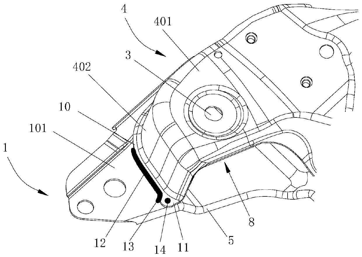
[0040] This embodiment relates to a method for installing a vehicle subframe structure as described in Embodiment 1. The method includes the following steps:

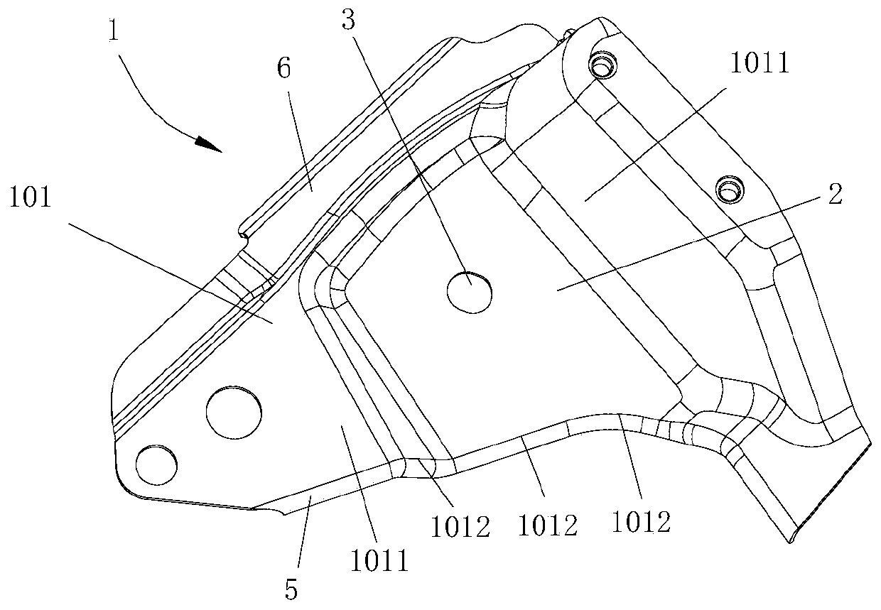
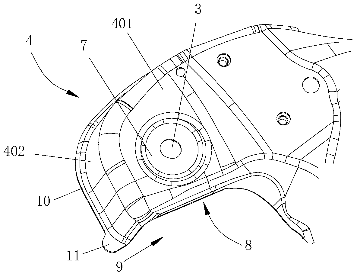
[0041] a) Place the upper board on the lower board, align the two mounting holes and fully contact and fit the lower surface of the flange 10 with the welding surface 1011, and connect the swing arm to the mounting hole 3 through the bolt assembly On the upper side board 4 and the lower side board 1;

[0042] b) Perform welding along the outer edges of the bonded flanging 10 and protrusion 11 and the lap surface 1011 with carbon dioxide shielded welding equipment to form the main weld 12 and the secondary weld 13;

[0043] c) At the spot welding position 14, the protrusion 11 and the lower side plate 1 are clamped by a spot welding equipment, and the protrusion 11 and the lower side plate 1 covered by the protrusion 11 are spot welded to complete the connection process.

[0044] Using the method described in this embodiment to ...


PUM


Abstract

The invention provides a vehicle auxiliary frame structure and a mounting method thereof. The vehicle auxiliary frame structure is provided with an upper edge plate, a lower edge plate and a connecting part, wherein the connecting part is integrally formed at the bottom of the upper edge plate, and the connecting part and the lower edge plate are arranged in an attached mode. The connecting part and the lower edge plate are connected in a welded mode to form a welded joint, the connecting part comprises a main connecting part body and an auxiliary connecting part body which is formed on at least one end portion of the main connecting part body, the welded joint comprises a main welded joint body following the main connecting part body in shape, and an auxiliary welded joint body, the auxiliary welded joint body follows the auxiliary connecting part body in shape due to guiding of the auxiliary connecting part body, and the auxiliary welded joint body and the main welded joint body forman inflection point at an intersection place. The vehicle auxiliary frame structure further comprises a point welding position located between the auxiliary connecting part body and the lower edge plate so as to form point welding connection between the auxiliary connecting part body and the lower edge plate, and the auxiliary welded joint body and point welding connection are simultaneously formed between the auxiliary connecting part body and the lower edge plate, so that welded joint connection and point welding connection jointly bear stress from the outside, the situation of stress concentration at the tail end of the welded joint can further be avoided, and the phenomenon of cracking of the welded joint is reduced.

Description

Technical field [0001] The present invention relates to the technical field of vehicle parts, in particular to a vehicle subframe structure. The invention also relates to an installation method of the vehicle subframe structure. Background technique [0002] In the field of automobile manufacturing technology, it is often necessary to weld and connect body parts (such as sheet metal parts and chassis parts). The car subframe in existing vehicles is composed of an upper side plate and a lower side plate. The upper side plate and the lower side plate are connected when they are connected. The bottom edge of the upper side board can be overlapped with the lower side board, and welded along the overlap edge to form a weld of a certain length. Due to the welding process and the structure of the sheet metal parts, especially stress concentration at the end of the weld, it is easy to crack the weld when the road conditions are complex, and cause the failure of the connection structure,...

Claims


Application Information

Patent Timeline
Patent Type & Authority Patents(China)
IPC IPC(8): B62D21/00B62D24/00
CPCB62D21/00B62D24/00
Inventor 常星亚王俊付敬阳宋东
Owner GREAT WALL MOTOR CO LTD
Why Eureka
Try Eureka