Two-stage air floatation type vibration reduction high-low temperature chamber accompanying system

A high and low temperature box and air flotation technology, which is applied in the direction of gas shock absorbers, shock absorbers, shock absorbers, etc., can solve problems such as unsatisfactory vibration isolation efficiency, high project budget, and increased construction period

Active Publication Date: 2018-07-10
国机集团科学技术研究院有限公司
View PDF8 Cites 6 Cited by
  • Summary
  • Abstract
  • Description
  • Claims
  • Application Information

AI Technical Summary

Problems solved by technology

[0003] 1) Low vibration isolation efficiency
The vibration source input of the high and low temperature box includes vibration equipment such as motors with high frequency and background vibration such as construction and people walking in the distance with low frequency. Vibrational response, may even cause resonance, so its vibration isolation efficiency is not ideal
Moreover, the damping of large-volume concrete is relatively small, and the energy-absorbing capacity is weak. When the high-low temperature chamber is calibrated or the speed-type specimen is tested, the vibration isolation efficiency of the large-volume concrete vibration isolation foundation cannot meet the requirements.
[0004] 2) Long construction period
The large-volume foundation construction process is complicated, the construction is difficult, and the temperature and stress of the large-volume concrete are not well controlled, resulting in a long construction period for vibration isolation of the large-volume foundation.
During the construction of m

Method used


Image

  • Two-stage air floatation type vibration reduction high-low temperature chamber accompanying system

Examples


Embodiment Construction

[0019] In order to make the object, technical solution and advantages of the present invention clearer, various embodiments of the present invention will be described in detail below in conjunction with the accompanying drawings. However, those of ordinary skill in the art can understand that, in each implementation manner of the present invention, many technical details are provided for readers to better understand the present application. However, even without these technical details and various changes and modifications based on the following implementation modes, the technical solution claimed in each claim of the present application can be realized.

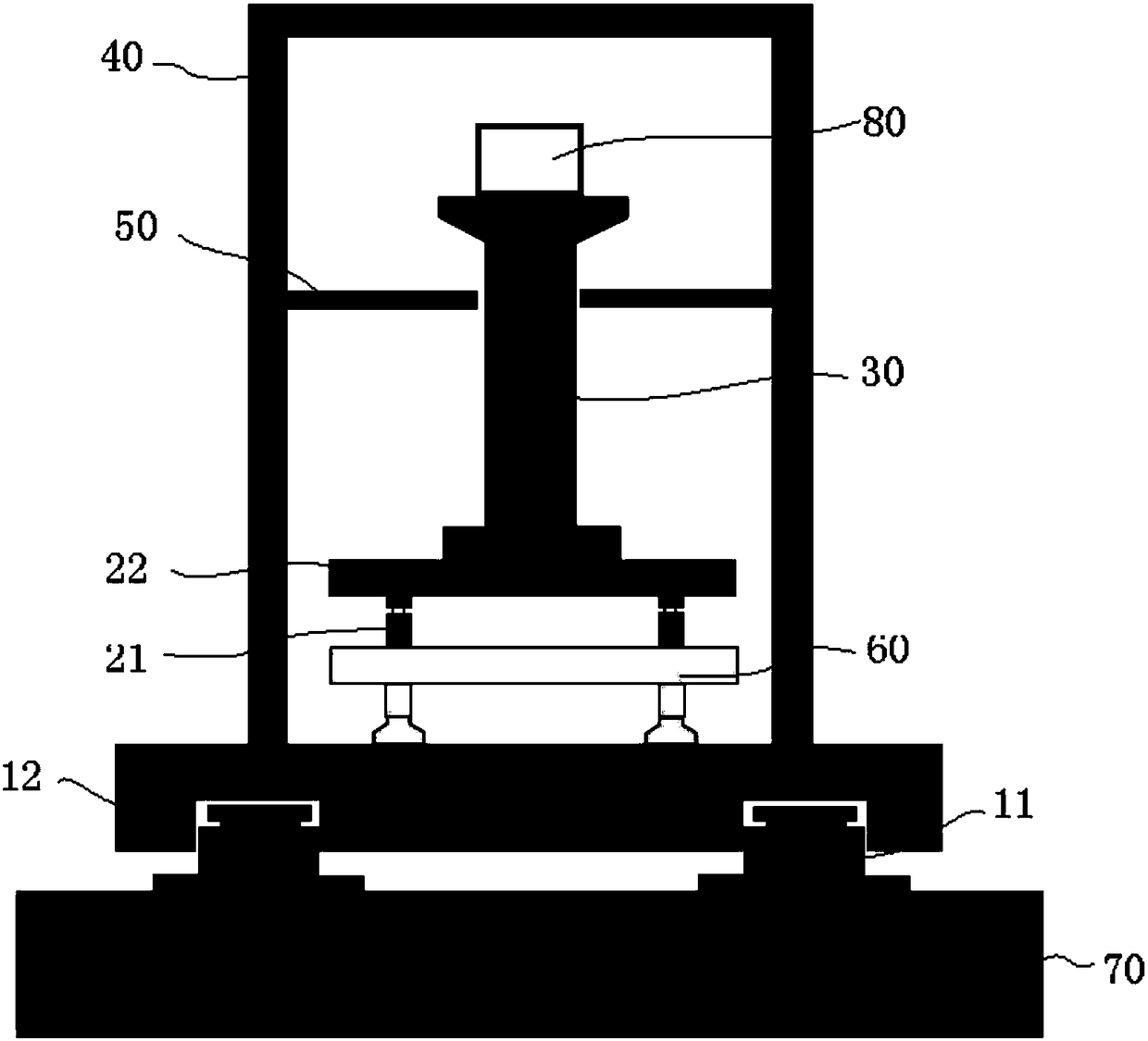
[0020] figure 1 It is a schematic diagram of a two-stage air flotation damping high and low temperature box accompanying system according to the present invention. refer to figure 1 , the ultra-long synchrotron radiation light source basic micro-nano level vibration control structure includes: a primary vibration damping d...


PUM


Abstract

The invention discloses a two-stage air floatation type vibration reduction high-low temperature chamber accompanying system. The accompanying system comprises a primary vibration reduction device, asecondary vibration isolation air floatation support frame, a secondary vibration reduction device, a test pillar and a high-low temperature chamber shell, wherein the primary vibration reduction device comprises a primary vibration reduction air spring unit and a primary vibration reduction rigid platform arranged on the primary vibration reduction air spring unit; the secondary vibration reduction device comprises a secondary vibration reduction air spring unit arranged on the secondary vibration isolation air floatation support frame and a secondary vibration isolation air floatation platform top plate arranged on the secondary vibration reduction air spring unit; the secondary vibration isolation air floatation support frame is arranged on the primary vibration reduction rigid platform; the test pillar is arranged on the secondary vibration isolation air floatation platform top plate; and the high-low temperature chamber shell is arranged on the primary vibration reduction rigid platform for sealing the secondary vibration isolation air floatation support frame, the secondary vibration reduction device and the test pillar.

Description

technical field [0001] The invention relates to the field of vibration control, in particular to a two-stage air flotation vibration damping high and low temperature box accompanying system. Background technique [0002] At present, in view of the vibration impact of high and low temperature boxes, the main measures are to avoid (stay away from) the vibration source or adopt large-volume foundation vibration isolation. Changes are difficult to control effectively. The main disadvantages of traditional methods are as follows: [0003] 1) Low vibration isolation efficiency. The vibration source input of the high and low temperature box includes vibration equipment such as motors with high frequency and background vibration such as construction and personnel walking in the distance with low frequency. Vibration response, and may even cause resonance, so its vibration isolation efficiency is not ideal. Moreover, the damping of large-volume concrete is relatively small, and t...

Claims


Application Information

Patent Timeline
IPC IPC(8): F16F9/02F16F9/32
Inventor 徐建张同亿伍文科张瑞宇曹雪生胡明祎黄伟秦敬伟兰日清祖晓臣
Owner 国机集团科学技术研究院有限公司
Why Eureka
Try Eureka