

Signal transmission method, device and system
A signal transmission and synchronization signal technology, applied in the field of communication, can solve problems such as increasing the complexity of terminal processing
- Summary
- Abstract
- Description
- Claims
- Application Information
AI Technical Summary
Problems solved by technology
Method used
Image

Examples
Embodiment 1
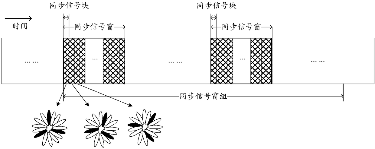
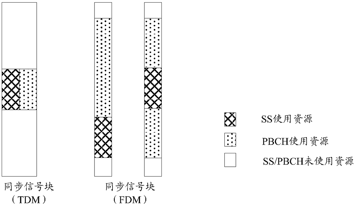
[0263] This embodiment describes using a subcarrier mapping manner of a synchronization signal at a certain level to indicate whether a synchronization signal block (SS block) where the synchronization signal is located contains a message signal. Wherein, the synchronization signal may include two stages, namely a primary synchronization signal (PSS, Primary Synchronization Signal) and a secondary synchronization signal (SSS, Secondary Synchronization Signal); the SSS sequence may include two subsequences, and the two subsequences adopt a comb-shaped subcarrier cross-mapping method, It is used to indicate the configuration mode of the sync signal block. In this embodiment, the message signal refers to a physical broadcast channel (PBCH).
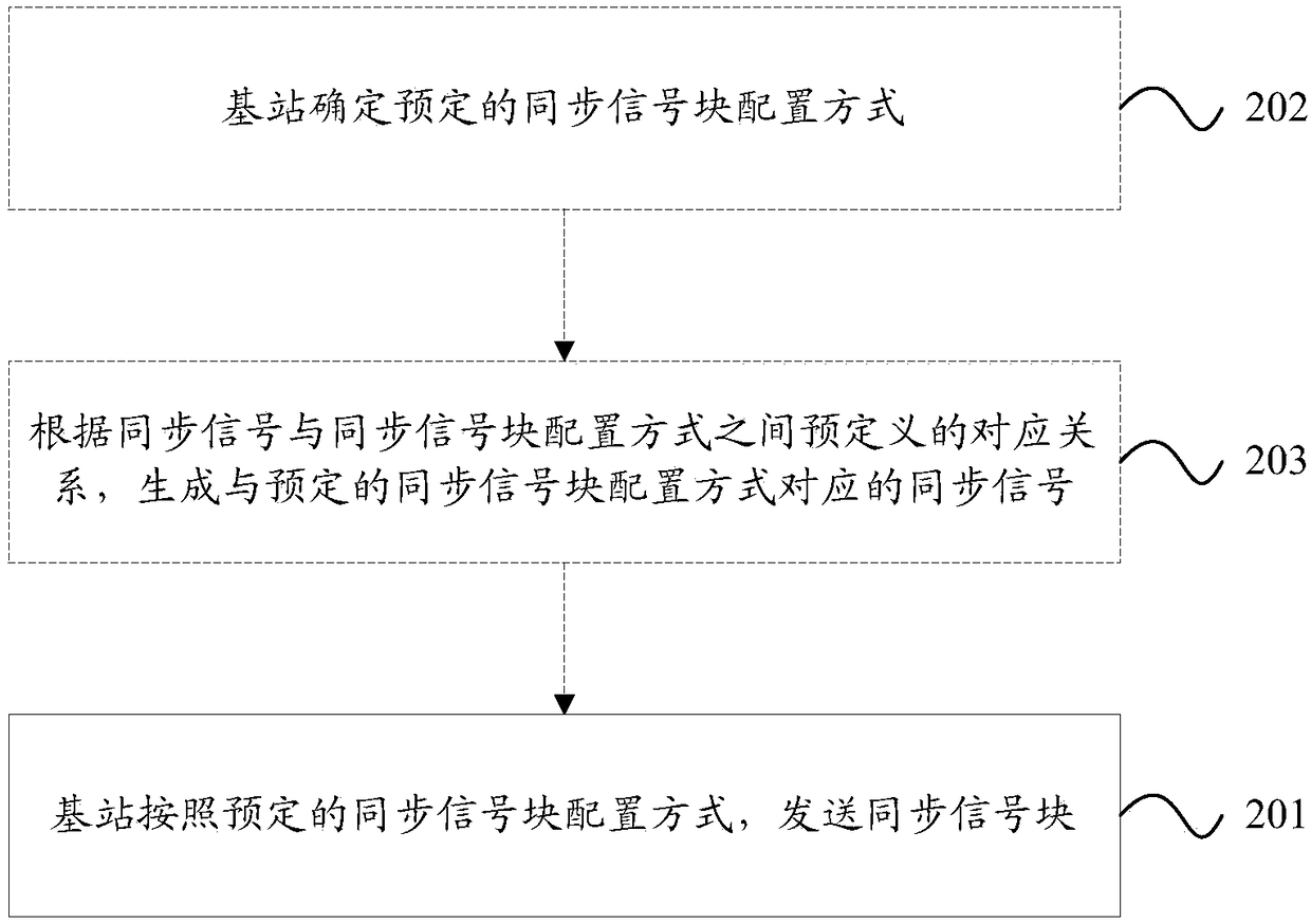
[0264] In this embodiment, the base station determines the transmission mode of the PBCH; wherein, the PBCH can carry one or more of the following information: system frame number (SFN), index of the synchronization signal block, index of th...
Embodiment 2
[0295] This embodiment describes using a subcarrier mapping manner of a synchronization signal of a certain level to indicate whether a message signal in a synchronization signal block (SS block) is repeatedly sent. Among them, the synchronization signal can include two levels, namely the primary synchronization signal (PSS) and the secondary synchronization signal (SSS); the SSS sequence can include two subsequences, using a comb-shaped subcarrier cross-mapping method, which is used to indicate the configuration of the synchronization signal block. In this embodiment, the message signal refers to a physical broadcast channel (PBCH).
[0296] In this embodiment, the base station determines the transmission mode of the PBCH, that is, whether the PBCH is repeatedly transmitted, such as Figure 11 As shown, there are but not limited to the following repetition methods:
[0297] Repeated transmission in the SS block, for example, time division transmission between two repetitions...
Embodiment 3
[0307] This embodiment describes the use of a subcarrier mapping manner of a synchronization signal at a certain level to indicate the number of times a message signal in a synchronization signal block (SS block) is repeatedly sent. Among them, the synchronization signal can include two levels, that is, the primary synchronization signal (PSS) and the secondary synchronization signal (SSS). The SSS sequence can include three sub-sequences, and the three sub-sequences use a comb-shaped sub-carrier cross-mapping method to indicate the synchronization signal block Configuration method. In this embodiment, the message signal refers to a physical broadcast channel (PBCH).
[0308] In this embodiment, the base station determines the transmission mode of the PBCH, that is, whether the PBCH is repeatedly transmitted, which exists but is not limited to Figure 12 Repeat as shown. Wherein, the number of repeated sending times is a parameter that needs to be indicated in this embodimen...
PUM
 Abstract
Description
Claims
Application Information