
LF furnace bottom argon blowing bi-branch flow control device

A flow control device and flow controller technology, applied in the direction of flow control, flow control using electric devices, non-electric variable control, etc., can solve the problems of complex structure of mechanical parts, short adjustment process, system vibration, etc., and achieve good control accuracy. and stability, the adjustment process is short, and the step response is fast.

Pending Publication Date: 2018-07-13
WEIER AUTOMATION CO LTD TANGSHAN IRON & STEELGRP
View PDF6 Cites 2 Cited by
  • Summary
  • Abstract
  • Description
  • Claims
  • Application Information

AI Technical Summary

Problems solved by technology

This system has a short adjustment process and a fast step response, but it has defects such as complex structure of mechanical parts, frequent switching operations, easy damage to components, single valve failure can cause system oscillation, poor fault tolerance, etc., and the high price is not conducive to popularization

Method used


Image

  • LF furnace bottom argon blowing bi-branch flow control device
  • LF furnace bottom argon blowing bi-branch flow control device
  • LF furnace bottom argon blowing bi-branch flow control device

Examples


Embodiment Construction

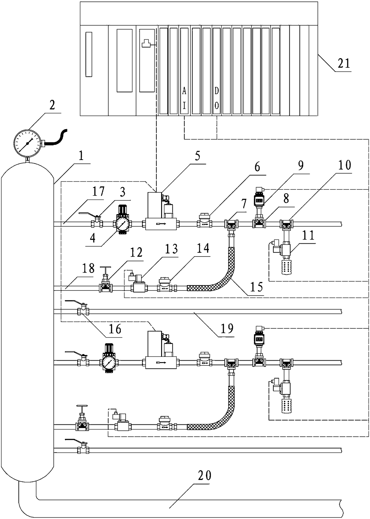
[0022] see figure 1 and figure 2 , the present invention mainly consists of a stabilized pressure distributor 1, a gas source pressure remote transmission meter 2, an argon blowing balloon valve 3, an overflow type pressure regulating unit 4, an integrated thermal mass flow controller 5, and a main blowing check valve 6 , 90-degree side blowing tee 7, 90-degree source tee 8, shock-resistant pressure display transmitter 9, 90-degree pressure relief tee 10, noise reduction and pressure relief unit 11, side blowing intake stop valve 12, side blowing Control unit 13, bypass check valve 14, rubber hose assembly 15, redundant inlet ball valve 16, PLC controller 21 and other stainless steel pipe fittings. The device is protected by a cabinet, and the size of the cabinet is H1600 x W1800 x D400. The connection method of the pipe fittings in the device is screw connection, and the connection thread is wrapped with Teflon tape. The right side of the inside of the box is the inlet and...


PUM


Abstract

An LF furnace bottom argon blowing bi-branch flow control device is composed of a pressure stabilizing distributor, two sets of argon blowing pipes and a PLC. The bottom of the pressure stabilizing distributor is connected with an argon source through a gas inlet pipe. Each set of the argon blowing pipe comprises a main blowing pipe, an argon blowing gas inlet ball valve, an overflow type pressureadjusting unit and an integrated heat type mass and flow controller, wherein one end of the main blowing pipe communicates with an inner cavity of the pressure stabilizing distributor, the other endof the main blowing pipe is connected with a steel ladle sequentially through the argon blowing gas inlet ball valve, the overflow type pressure adjusting unit and the integrated heat type mass and flow controller, and the integrated heat type mass and flow controller is connected with the PLC through an industrial bus. According to the LF furnace bottom argon blowing bi-branch flow control device, the argon flow control of the two sets of argon blowing pipes is completed both through the PLC and the integrated heat type mass and flow controllers, the adjusting process is short, the step response is rapid, good control precision and stability are achieved, and the LF furnace bottom argon blowing bi-branch flow control device is simple in structure, low in cost, reliable in running and suitable for being applied and popularized in the metallurgy industry.

Description

technical field [0001] The invention relates to an argon flow control device used for bottom-blown argon stirring in the LF furnace smelting process, and belongs to the technical field of metal smelting. Background technique [0002] During the refining process of the LF furnace, a stirring process of blowing argon gas at the bottom of the ladle is required. After the argon gas enters the bottom of the ladle, the floating argon gas bubbles drive the molten steel in the ladle to do a reciprocating up and down motion to make the molten steel evenly mixed. At the same time, the argon gas bubbles can absorb and release harmful gas impurities in the molten steel to improve the smelting quality. The flow rate of argon needs to be adjusted according to the arc smelting process. If it is too large, the violent movement of molten steel will affect the control of the arc and easily form slag defects. If it is too small, the purpose of stirring molten steel will not be achieved and the...

Claims


Application Information

Patent Timeline
IPC IPC(8): C21C7/072G05D7/06G05B11/42
CPCG05B11/42G05D7/0641C21C7/072Y02P10/25
Inventor 刘海朝张丽王令武世卿叶楠孙立彬严彪姚辉贾会华
Owner WEIER AUTOMATION CO LTD TANGSHAN IRON & STEELGRP
Learn More