Manufacturing method of flexible display device and flexible display device

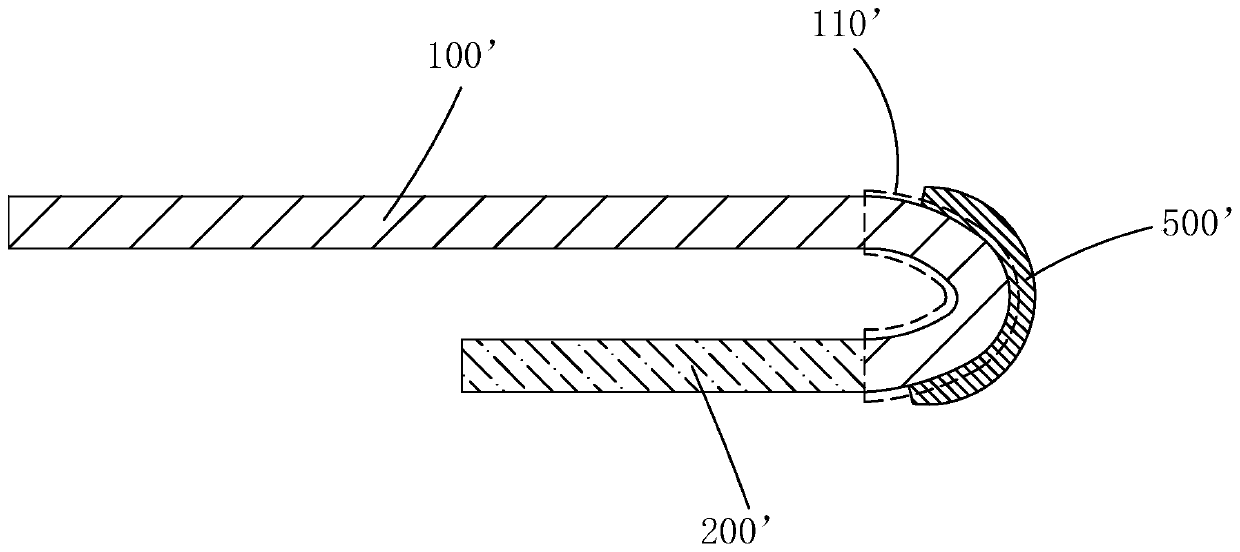
A flexible display device and flexible display technology, which are applied in identification devices, final product manufacturing, climate sustainability, etc., can solve the problems of increasing the difficulty of bending, line damage, and increasing the stress of the bending area 110', and reduce the Difficulty of bending, stress prevention, stress reduction effect

Active Publication Date: 2019-09-24
WUHAN CHINA STAR OPTOELECTRONICS SEMICON DISPLAY TECH CO LTD
View PDF4 Cites 0 Cited by
  • Summary
  • Abstract
  • Description
  • Claims
  • Application Information

AI Technical Summary

Problems solved by technology

see figure 1 , is an existing flexible display device, including a flexible display panel 100' and a flexible printed circuit (Flexible Printed Circuit, FPC) 200' bound to the flexible display panel 100', and one end of the flexible display panel 100' is set There is a bending area 110', the flexible circuit board 200' is bound to the bending area 110' of the flexible display panel 100', and the bending area 110' of the flexible display panel 100' faces the flexible display panel 100'. The back is bent to reduce the width of the border of the display device and increase the screen-to-body ratio. In the prior art, before the bending region 110' of the flexible display panel 100' is bent, the front of the flexible display panel 100' is bent correspondingly. The folding area 110' is coated with a layer of protective adhesive layer 500' (such as UV-curable adhesive) and cured, and then the bending area 110' of the flexible display panel 100' and the protective adhesive layer 500' on it are placed on the flexible display panel. The back side of 100' is curved, and the protective adhesive layer 500' is provided to protect the bending area 110' of the flexible display panel 100'. However, the thickness of the protective adhesive layer 500' is smaller than that of the flexible substrate in the flexible display panel 100'. thicker, and it has a higher hardness after being cured, which greatly increases the difficulty of bending the bending region 110' of the flexible display panel 100', and increases the stress on the bending region 110' during bending. Damage to the wires within the bend region 110'

Method used


Image

  • Manufacturing method of flexible display device and flexible display device
  • Manufacturing method of flexible display device and flexible display device
  • Manufacturing method of flexible display device and flexible display device

Examples


no. 1 example

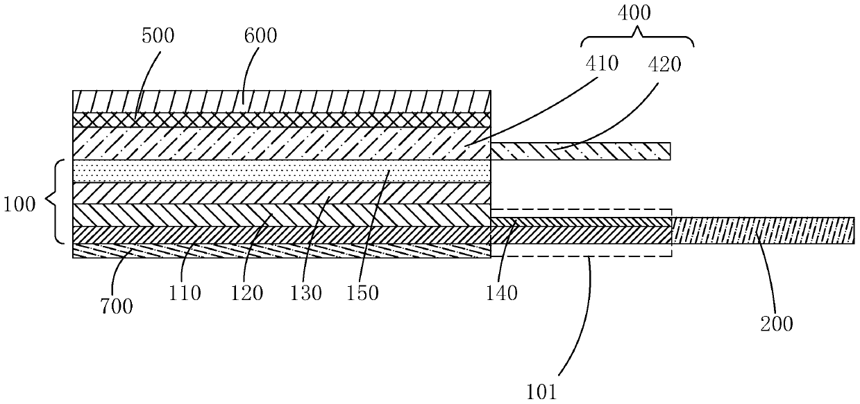
[0056] Based on the same inventive concept, the present invention also provides a flexible display device manufactured by the above-mentioned manufacturing method of the flexible display device, please refer to Figure 5 , is the first embodiment of the flexible display device of the present invention, and the flexible display device includes: a flexible display panel 100, a flexible circuit board 200 bound to the flexible display panel 100, and a first protective glue disposed on the flexible display panel 100 Layer 310;

[0057] The flexible display panel 100 has a bending area 101 at one end thereof, and the flexible circuit board 200 is bound to the bending area 101 of the flexible display panel 100; the bending area 101 of the flexible display panel 100 faces the flexible display panel The back side of the flexible display panel 100 is curved; the first protective adhesive layer 310 is located on the front side of the flexible display panel 100 corresponding to the bendin...


PUM


Abstract

The invention provides a manufacturing method of a flexible display device and the flexible display device. In the manufacturing method of the flexible display device of the present invention, the bending area of ​​the flexible display panel is first bound to the flexible circuit board, then the bending area of ​​the flexible display panel is bent toward the back of the flexible display panel, and then the flexible display panel Making the first protective adhesive layer on the front side of the flexible display panel corresponding to the bending area. The first protective adhesive layer is used to protect the wiring in the bending area, and at the same time, since the first protective layer is formed after the bending area is bent, compared with the prior art, the bending area of ​​the flexible display panel is reduced. Difficulty, reduce the stress on the bending area of ​​the flexible display panel during bending, and improve product quality.

Description

technical field [0001] The invention relates to the field of display technology, in particular to a method for manufacturing a flexible display device and the flexible display device. Background technique [0002] Organic Light Emitting Display (OLED) has self-illumination, low driving voltage, high luminous efficiency, short response time, high definition and contrast, nearly 180° viewing angle, wide operating temperature range, and can realize flexible display and With many advantages such as large-area full-color display, it is recognized by the industry as a display device with the most potential for development. [0003] OLED devices generally include: a substrate, an anode disposed on the substrate, a hole injection layer disposed on the anode, a hole transport layer disposed on the hole injection layer, a light emitting layer disposed on the hole transport layer, a An electron transport layer on the light emitting layer, an electron injection layer on the electron tr...

Claims


Application Information

Patent Timeline
Patent Type & Authority Patents(China)
IPC IPC(8): H01L23/00H01L27/32G09F9/33
CPCH01L23/562G09F9/33H10K59/12H10K59/1201G09F9/301Y02E10/549Y02P70/50H10K77/111H10K50/844H10K2102/311H10K71/00H10K59/131H10K59/1213
Inventor 王明亮王思元
Owner WUHAN CHINA STAR OPTOELECTRONICS SEMICON DISPLAY TECH CO LTD
Why Eureka
Try Eureka