A method to improve the pm of iron ore sintering flue gas electric dust removal process 2.5 The method of removal efficiency

A technology for sintering flue gas and removal efficiency, which is applied in the field of improving the removal efficiency of PM2.5 in the electric dust removal process of iron ore sintering flue gas, and in the field of sintering flue gas treatment. It can solve the problems of low emission concentration, large sintering flue gas flow rate, Implementation and other issues to achieve the effect of improving conductivity

Active Publication Date: 2020-12-04
CENT SOUTH UNIV +1
View PDF2 Cites 0 Cited by
  • Summary
  • Abstract
  • Description
  • Claims
  • Application Information

AI Technical Summary

Problems solved by technology

Due to the disadvantages of introducing new impurities into the mixture or being difficult to implement in the sinter layer due to the addition of solid and gas adsorbents, the process adsorption technology cannot meet the needs of sintering; due to the large flow of sintering flue gas (about 3000-4300m from 1t sinter 3 Exhaust gas), PM 2.5 The emission concentration is low, and it is difficult to obtain efficient and low-cost application of agglomeration pretreatment technology
Therefore, the above-mentioned control technologies are difficult to be directly transplanted to the field of iron ore sintering, and currently there is still a lack of feasible sintering flue gas PM 2.5 governance technology

Method used


Image

  • A method to improve the pm of iron ore sintering flue gas electric dust removal process  <sub>2.5</sub> The method of removal efficiency
  • A method to improve the pm of iron ore sintering flue gas electric dust removal process  <sub>2.5</sub> The method of removal efficiency

Examples


Embodiment 1

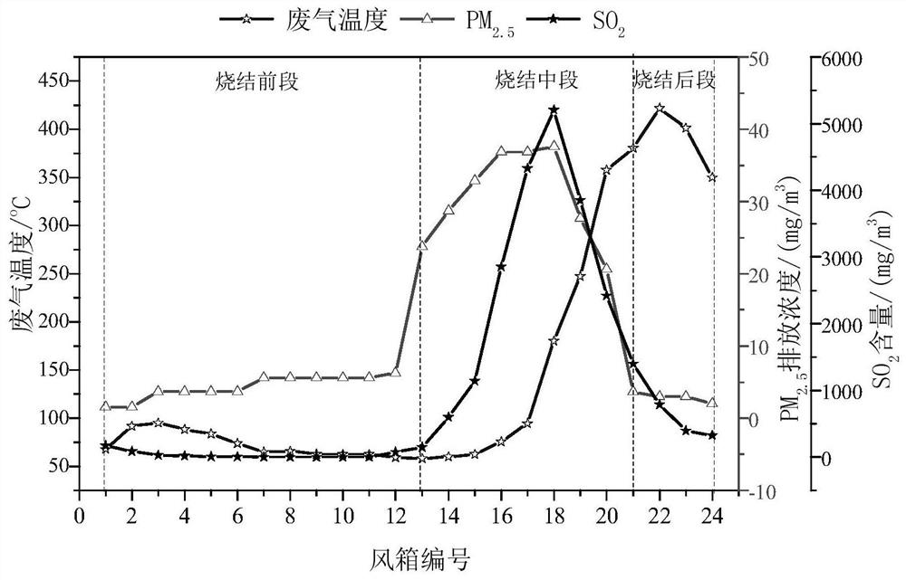
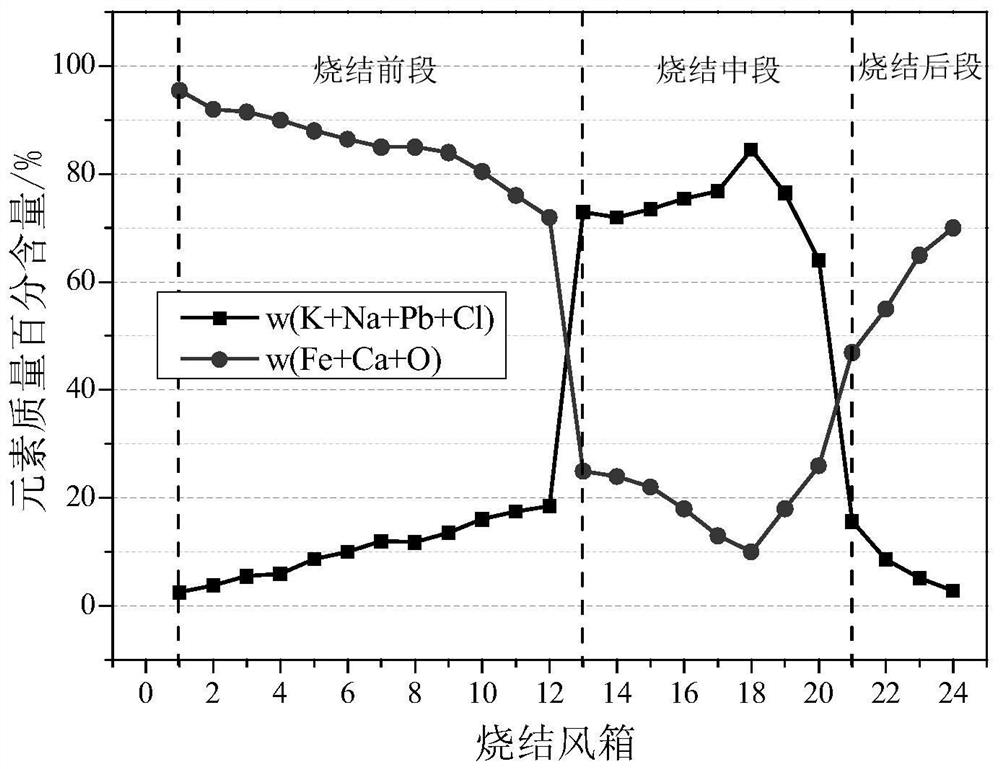
[0029] According to the PM emitted from flue gas in different wind boxes of sintering trolley 2.5 , SO 2 Emission concentration (see figure 1 ) and PM 2.5 chemical composition (see figure 2 ) change law, the sintering flue gas is divided into three sections, specifically: 1 # Bellows to 12 # The bellows is the front section of sintering, 13 # Bellows to 20 # The bellows is divided into a sintered middle section, 21 # Bellows to 24 # The bellows is the post-sintering section. Will 1 # -12 # The flue gas from the bellows is introduced into the low-temperature flue, and the 13 # -20 # The flue gas from the bellows is introduced into the medium temperature bellows; adjust 21 # -twenty four # The proportion of the high-temperature hot exhaust gas from the bellows entering the medium-temperature flue makes the flue gas temperature reach 180°C, and the rest of the high-temperature flue gas is introduced into the low-temperature flue to make its temperature higher than ...

Embodiment 2

[0031] According to the PM emitted from flue gas in different wind boxes of sintering trolley 2.5 , SO 2 Emission concentration (see figure 1 ) and PM 2.5 chemical composition (see figure 2 ) change law, the sintering flue gas is divided into three sections, specifically: 1 # Bellows to 12 # The bellows is the front section of sintering, 13 # Bellows to 20 # The bellows is divided into a sintered middle section, 21 # Bellows to 24 # The bellows is the post-sintering section. Will 1 # -12 # The flue gas from the bellows is introduced into the low-temperature flue, and the 13 # -20 # The flue gas from the bellows is introduced into the medium temperature bellows; adjust 21 # -twenty four # The proportion of the high-temperature hot exhaust gas from the bellows entering the medium-temperature flue makes the flue gas temperature reach 200°C, and the rest of the high-temperature flue gas is introduced into the low-temperature flue to make its temperature higher than ...

Embodiment 3

[0033] According to the PM emitted from flue gas in different wind boxes of sintering trolley 2.5 , SO 2 Emission concentration (see figure 1 ) and PM 2.5 chemical composition (see figure 2 ) change law, the sintering flue gas is divided into three sections, specifically: 1 # Bellows to 12 # The bellows is the front section of sintering, 13 # Bellows to 20 # The bellows is divided into a sintered middle section, 21 # Bellows to 24 # The bellows is the post-sintering section. Will 1 # -12 # The flue gas from the bellows is introduced into the low-temperature flue, and the 13 # -20 # The flue gas from the bellows is introduced into the medium temperature bellows; adjust 21 # -twenty four # The proportion of high-temperature hot exhaust gas from the bellows entering the medium-temperature flue makes the flue gas temperature reach 220°C, and the remaining high-temperature flue gas is introduced into the low-temperature flue to make its temperature higher than the ac...


PUM


Abstract

The invention discloses a method of improving PM2.5 removal efficiency in an electric precipitation process of iron ore sintering smoke. The method comprises the steps of dividing the smoke generatedby sintering into sintering front section smoke (a low PM2.5 emission concentration, and mainly comprising Fe, Ca and O), sintering middle section smoke (a high PM2.5 emission concentration and mainlycomprising K, Na, Pb and Cl) and sintering rear section smoke (a low PM2.5 emission concentration and high smoke temperature), leading the sintering front section smoke and the middle section smoke into a low temperature flue and a middle temperature flue, regulating the temperature of the low temperature flue to be higher than an acid dew point and the temperature of the middle temperature flueto 180-220 DEG C via the sintering rear section smoke, spraying a smoke conditioning agent into the middle temperature flue at the same time, and removing PM2.5 from the smoke in the two flues via a conventional electrostatic precipitator. The PM2.5 removal efficiency of the electric precipitator is improved by sintering smoke segmentation, flue temperature regulating, and regulating of a PM2.5 ingredient in the smoke and specific resistance by spraying the conditioning agent.

Description

technical field [0001] The invention relates to a treatment method for sintering flue gas, in particular to a method for improving PM in the electric dust removal process of iron ore sintering flue gas. 2.5 The invention relates to a method for removing efficiency; it belongs to the technical field of iron and steel metallurgy flue gas treatment. Background technique [0002] PM 2.5 Refers to particles with an aerodynamic diameter of less than or equal to 2.5 μm, which can enter the alveoli of the human body, so they are also called lung-entering particles. Because of its small particle size and large specific surface area, it is easy to load heavy metals (Pb, Zn, As, Hg, etc.), persistent organic pollutants (PCDD / Fs, PCBs, etc.), germs and other toxic and harmful substances, which pose a serious threat to human health. threaten. In recent years, severe smog that frequently occurs in large and medium-sized cities in my country is mainly caused by PM emitted by industrial ...

Claims


Application Information

Patent Timeline
Patent Type & Authority Patents(China)
IPC IPC(8): B01D53/76B01D53/50B03C3/014
CPCB01D53/50B01D53/76B01D2251/104B03C3/014
Inventor 季志云甘敏范晓慧周志安陈许玲姜涛李光辉王兆才刘水石袁礼顺吕薇汪国靖周阳姚佳文王壮壮郑如月肖永贤王巧黄柱成杨永斌郭宇峰
Owner CENT SOUTH UNIV
Why Eureka
Try Eureka