
Plate ice machine with single-plate evaporator and operation method of plate ice machine

An evaporator and plate ice machine technology, applied in the field of machinery, can solve the problems of waste of refrigerant cooling capacity, low refrigerant heat exchange efficiency, poor plate ice thickness, etc., to enhance the heat exchange effect, extend the length of the flow path, The effect of prolonging the residence time

Inactive Publication Date: 2018-07-17
青岛华友冰雪制冷工程有限公司
View PDF6 Cites 0 Cited by
  • Summary
  • Abstract
  • Description
  • Claims
  • Application Information

AI Technical Summary

Problems solved by technology

[0005] The heat exchange efficiency of the refrigerant in the evaporator is low, which makes a large amount of cooling loss carried by the refrigerant waste
Refrigerant stays in the evaporator for a short time, which makes the working efficiency of unit refrigerant low, thus increasing the working time and workload of the compressor
The cooling effect of the evaporator is average, and the thickness of the plate ice produced is poor, and it is not suitable for storage, and it is easy to melt

Method used


Image

  • Plate ice machine with single-plate evaporator and operation method of plate ice machine
  • Plate ice machine with single-plate evaporator and operation method of plate ice machine
  • Plate ice machine with single-plate evaporator and operation method of plate ice machine

Examples


Embodiment Construction

[0034] The following are specific embodiments of the present invention and in conjunction with the accompanying drawings, the technical solutions of the present invention are further described, but the present invention is not limited to these embodiments.

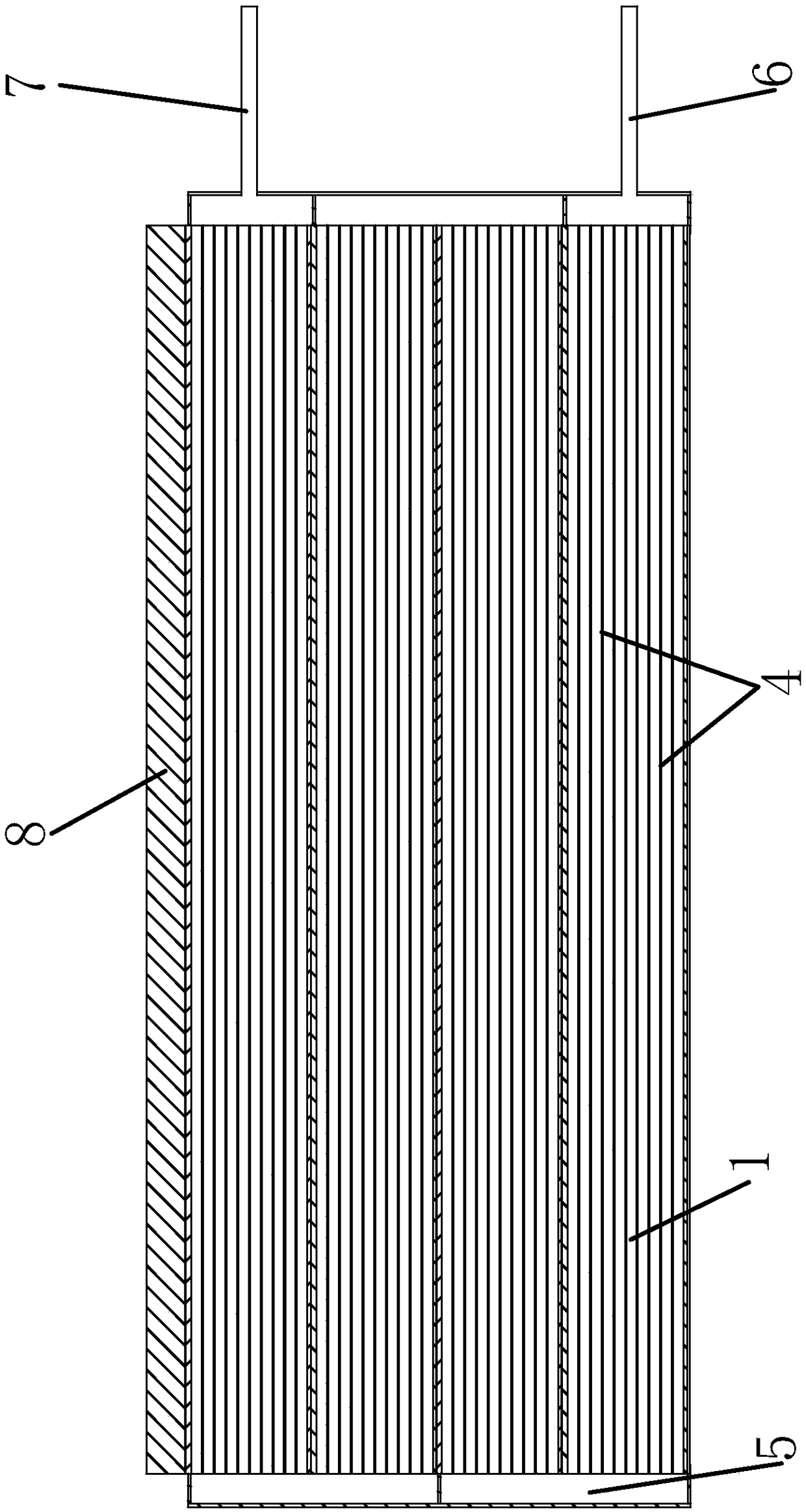
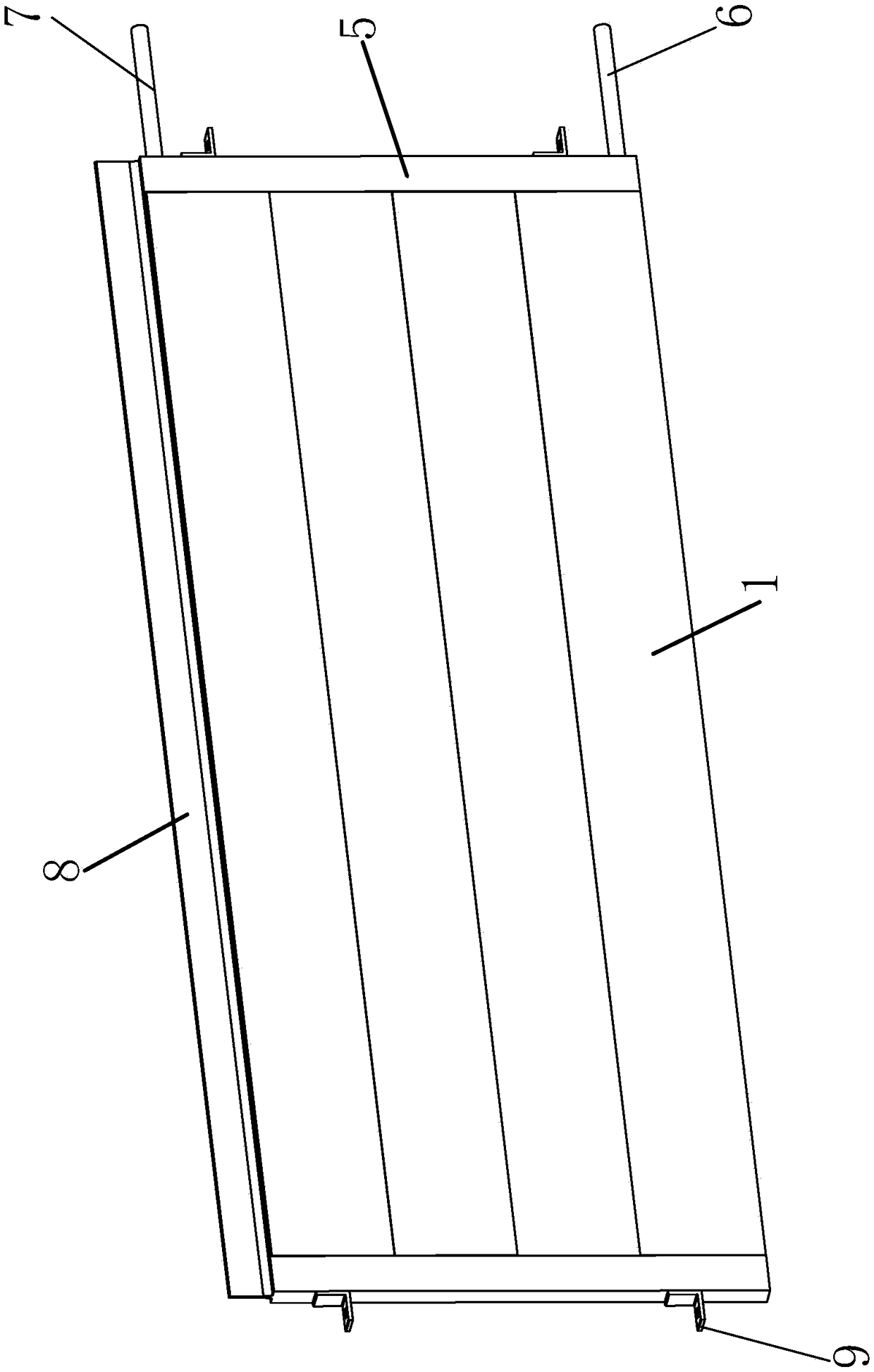
[0035] Such as Figure 1 to Figure 6As shown, the plate ice machine with a single-plate evaporator includes a fuselage shell 10, and a refrigeration system and a water delivery system are arranged in the fuselage shell 10. The refrigeration system includes a compressor connected in a loop, a condenser 20, an expansion valve and The evaporator and the water delivery system include a circulating water tank 14 connected in circulation, a water pump 15, a water supply pipe 16 and a sprinkler tank 17, and an inspection port 11 and an ice outlet 12 are set on the front of the fuselage shell 10, and the evaporator includes a parallel arrangement of Several evaporation veneers 18, the evaporation veneers 18 include several unit pl...


PUM

PropertyMeasurementUnit
Widthaaaaaaaaaa
Heightaaaaaaaaaa

Abstract

The invention provides a plate ice machine with a single-plate evaporator and an operation method of the plate ice machine. A refrigerating system and a water conveying system are arranged in the machine body shell of the plate ice machine, wherein the evaporator comprises a plurality of evaporation single plates; the evaporation single plates comprise a plurality of unit plate bodies, a pluralityof circulating channels are horizontally arranged in the unit plate bodies, and blocking plates are fixedly arranged on the two sides of the unit plate bodies; cavities are formed in the blocking plates, one ends of the inner cavities of the blocking plates are opened, sealing plates are arranged at the other ends, and the openings of the cavities of the two blocking plates on the same unit blocking plate are arranged in an up-and-down reversed mode; the plurality of unit plate bodies are fixedly connected through the splicing assembly in a longitudinal arranging mode, and the blocking platesof the upper and lower adjacent unit plate bodies are connected in a butt joint mode, so that the cavities of the connecting blocking plates are communicated in a sealed mode; liquid supply openingsare formed, in the blocking plates, of one sides of the unit plate bodies at the bottommost part, and liquid return openings are formed, in the blocking plates, of one sides of the unit plate bodies located at the uppermost part; and the liquid supply openings of the plurality of evaporation single plates are connected with liquid supply pipes in a collecting way, and the liquid return openings ofthe plurality of evaporation single plates are connected with the liquid return pipes.

Description

technical field [0001] The invention belongs to the technical field of machinery, and relates to an ice-making device, in particular to a plate ice machine with a single-plate evaporator and an operating method thereof. Background technique [0002] Plate ice machine is a kind of ice machine, generally industrial ice machine. The ice produced is in block form. The plate ice produced by it is irregular, hard, transparent and dry. The thickness and width of the plate ice can be adjusted freely according to the purpose. In the commercial field, it is used in the fresh and frozen meat preservation booths of large supermarkets; hotels, guesthouses; aquatic product monopoly and wholesale markets. Food processing industry: fresh-keeping and cooling of broiler and other meat processing; fresh-keeping of vegetables, milk and coffee; cooling of bread processing and wine making. Aquatic product processing industry: grilled eel, shrimp products, fish and other non-staple food proces...

Claims


Application Information

Patent Timeline
IPC IPC(8): F25C1/12F25B39/02
CPCF25B39/022F25C1/12
Inventor 独孤勇
Owner 青岛华友冰雪制冷工程有限公司
Learn More