Cavity multi-field coupling equation of cavity and boundary condition establishing method

A technology of boundary conditions and establishment methods, applied in special data processing applications, instruments, electrical and digital data processing, etc., can solve problems such as reducing the ability to guide experimental and numerical calculation results, reducing research efficiency, and increasing research costs.

Active Publication Date: 2018-07-17
INST OF HIGH SPEED AERODYNAMICS OF CHINA AERODYNAMICS RES & DEV CENT
View PDF5 Cites 1 Cited by
  • Summary
  • Abstract
  • Description
  • Claims
  • Application Information

AI Technical Summary

Problems solved by technology

[0003] At present, the complexity of cavity flow/vibration/noise multi-field coupling problems is significantly higher than that of cavity single-physics problems, and cavity multi-field coupling equations and coupling boundary conditions are rare. Based on fluid mechanics, aeroacoustics, The basic principles of structural dynamics, the systematic establishment of equations for cavity multi-field coupling problems, and the proposal of cavity multi-field coupling boundary conditions are of great significance for further improving the research ability of cavity problems and expanding the scope of research, and can also make up for traditional research methods. These deficiencies a...

Method used


Image

  • Cavity multi-field coupling equation of cavity and boundary condition establishing method
  • Cavity multi-field coupling equation of cavity and boundary condition establishing method
  • Cavity multi-field coupling equation of cavity and boundary condition establishing method

Examples


Embodiment 1

[0110] The present invention is realized through the following technical scheme, a method for establishing cavity multi-field coupling equations and boundary conditions, establishing cavity multi-field coupling boundary conditions based on cavity flow control equations, cavity noise control equations and cavity structure vibration control equations .

[0111] It should be noted that, starting from the basic principles of fluid mechanics, aeroacoustics and structural dynamics, the present invention establishes a cavity flow / vibration / noise multi-field coupling equation, which can fundamentally ensure the correctness of the established equation; according to the cavity flow , vibration and noise coupling characteristics, and established the cavity multi-field coupling boundary conditions, which is conducive to grasping the essence and key parameters of the cavity multi-field coupling problem, and has a positive guiding role for the experimental and numerical research of cavity pr...

Embodiment 2

[0114] A method for establishing cavity multi-field coupling equations and boundary conditions, based on cavity flow control equations, cavity noise control equations and cavity structure vibration control equations to establish cavity multi-field coupling boundary conditions.

[0115] Further, in order to better realize the present invention, specifically include the following steps:

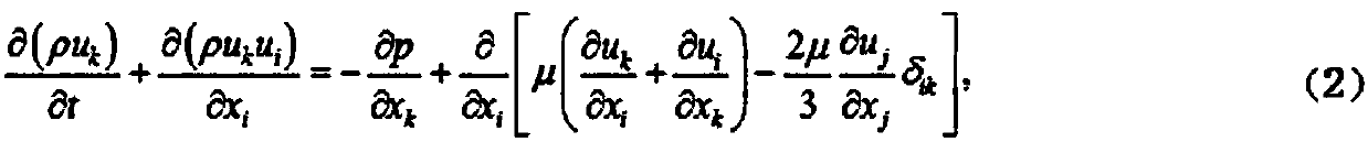
[0116] Step S1: establish the cavity flow control equation; specifically refers to: according to the basic law of the cavity flow, the hydrodynamic assumption is made, and the cavity flow control equation is established based on the basic principles of fluid mechanics; the step S1 specifically refers to: assuming the incoming flow The medium satisfies the ideal gas assumption and the Stokes assumption, using the mass conservation, momentum conservation and energy conservation relations, the cavity flow satisfies the equation:

[0117]

[0118]

[0119]

[0120] p=ρRT, e=C v T (4)

[...


PUM


Abstract

The invention discloses a cavity multi-field coupling equation and a boundary condition establishing method. A cavity multi-field coupling boundary condition is established based on a cavity flow control equation, a cavity noise control equation and a cavity structure vibration control equation. The method has the advantages that the method starts from basic principles of hydrodynamics, aeroacoustics and structural dynamics, and establishes the multi-field coupling equation of cavity flow/vibration/noise, and can ensure the correctness of the established equation fundamentally; based on the coupling characteristics of the cavity flow, vibration and noise, the cavity multi-field coupling boundary condition is established, which is beneficial for grasping the essence and key parameters of cavity multi-field coupling problems, the method has positive guidance for experimental and numerical researches of cavity type problems, and the research efficiency can be improved; the cavity multi-field coupling equation and the cavity boundary conditions are established in consideration of vibration problems of a cavity structure, which makes a research model closer to actual cavity problem, thereby improving the simulation ability of the cavity type problems.

Description

technical field [0001] The invention relates to the interdisciplinary technical fields of fluid mechanics, aeroacoustics and structural dynamics, and specifically relates to a cavity multi-field coupling equation and a method for establishing boundary conditions. Background technique [0002] Cavity flow is a typical unsteady and nonlinear flow phenomenon, especially under the condition of high-speed incoming flow, the gas flow velocity in the cavity is low, and the gas flow velocity outside the cavity is high, and gas with different flow velocities will form in the opening area of ​​the cavity. The transition layer, which is called the shear layer. When the shear layer hits the wall surface of the cavity, flow-induced oscillations are prone to occur in the cavity, resulting in high-intensity aerodynamic noise, and the high-intensity noise environment easily leads to fatigue of the cavity structure, and changes the flow field and sound field of the cavity. The boundary cond...

Claims


Application Information

Patent Timeline
IPC IPC(8): G06F17/50
CPCG06F30/20G06F2119/06G06F2119/10
Inventor 王显圣杨党国刘俊周方奇施傲杨野
Owner INST OF HIGH SPEED AERODYNAMICS OF CHINA AERODYNAMICS RES & DEV CENT
Why Eureka
Try Eureka