Information exchange method, device and system

A technology of information interaction and object information, which is applied in the field of image processing, can solve the problems of low image processing efficiency, cumbersome and complicated interaction methods, and complex implementation, and achieve the effects of improving image processing efficiency, improving interaction methods, and simplifying the amount of processing

Active Publication Date: 2018-07-17
AXERA SEMICON (SHANGHAI) CO LTD
View PDF5 Cites 2 Cited by
  • Summary
  • Abstract
  • Description
  • Claims
  • Application Information

AI Technical Summary

Problems solved by technology

In the process of interactive communication, the IPC main control chip needs to determine the image processing operation based on the detection information returned by the capture chip, which is relatively complicated to implement.
[0004] It can be seen from the above capture machine process that the interaction between the main control chip and the image detection chip in the existing image processing equipment is cumbersome and complicated, and the image processing efficiency is low

Method used


Image

  • Information exchange method, device and system
  • Information exchange method, device and system
  • Information exchange method, device and system

Examples


Embodiment 1

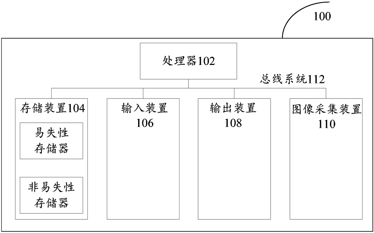
[0040] First, refer to figure 1 An example electronic device 100 for implementing the information interaction method, device and system of the embodiments of the present invention will be described.

[0041] like figure 1 Shown is a schematic structural diagram of an electronic device. The electronic device 100 includes one or more processors 102, one or more storage devices 104, an input device 106, an output device 108, and an image acquisition device 110. These components pass through a bus system 112 and / or other forms of connection mechanisms (not shown). It should be noted that figure 1 The components and structure of the electronic device 100 shown are only exemplary, not limiting, and the electronic device may also have other components and structures as required.

[0042] The processor 102 can be implemented in at least one hardware form of a digital signal processor (DSP), a field programmable gate array (FPGA), and a programmable logic array (PLA), and the proces...

Embodiment 2

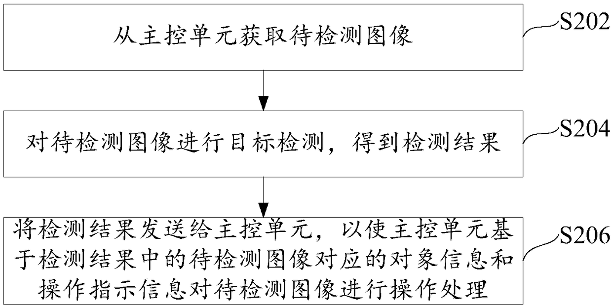
[0049] refer to figure 2 A flowchart of an information interaction method based on an image detection unit is shown, the method is executed by the image detection unit, and specifically includes the following steps:

[0050] Step S202, acquiring the image to be detected from the main control unit. The number of images to be detected may be one or multiple. For example, if it is a face recognizer that collects face images once or an image acquisition device that captures images periodically, the image to be detected can be only one captured image; if it is a capture machine that collects video data, the images to be detected can be multiple frame image.

[0051] In one embodiment, when the image to be detected is a frame image in the video stream, the method of acquiring the image to be detected may specifically be as follows: the image detection unit receives the video data transmitted by the main control unit; The images are respectively used as images to be detected.

...

Embodiment 3

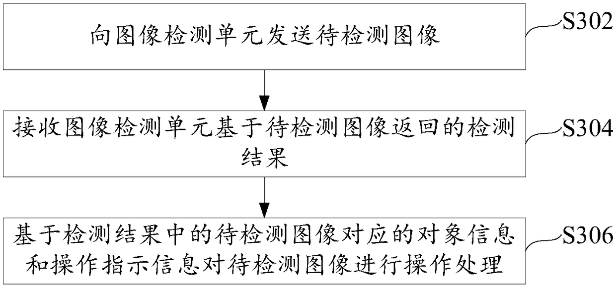
[0063] refer to image 3 A flow chart of an information interaction method based on the main control unit is shown, the method is executed by the main control unit, and specifically includes the following steps:

[0064] Step S302, sending the image to be detected to the image detection unit. During specific implementation, the video data may be sent to the image detection unit; wherein, each frame image in the video data is an image to be detected.

[0065] Step S304, receiving the detection result returned by the image detection unit based on the image to be detected; wherein, the detection result includes object information and operation instruction information corresponding to the image to be detected; the object information is the information of the target object in the image to be detected. During specific implementation, the received image detection unit returns detection results corresponding to each frame image based on each frame image; the detection result also inc...


PUM


Abstract

The invention provides an information exchange method, a device and a system thereof, wherein the method, the device and the system relate to the field of image processing technology. The informationexchange method which is executed by an image testing unit comprises the steps of acquiring a to-be-tested image from a master control unit; performing target testing on a the to-be-tested image, thereby obtaining a testing result; wherein the testing result comprises object information and operation indication information which correspond with the to-be-tested image; the object information is theinformation of the target object in the to-be-tested image; and transmitting a testing result to a master control unit so that the master control unit performs operation processing on the to-be-tested image based on the object information and the operation indication information that correspond with the to-be-tested image in the testing result. The information exchange method, the device and thesystem can simplify an exchange mode between a master control chip and an image testing chip in image processing equipment, thereby improving image processing efficiency.

Description

technical field [0001] The present invention relates to the technical field of image processing, in particular to an information interaction method, device and system. Background technique [0002] When the image processing equipment detects and processes the collected images, most of them require information interaction between the main control chip and the image detection chip. Taking the capture machine as an example, the main control chip can be an IPC (Internet Protocol Camera, network protocol camera) main control chip, which is used to collect video frames, and perform operations such as buffering, transmission, cutout, frame, and push of video frames , the image detection chip (also called a capture chip) is mainly used to detect video frame images to provide detection results to the main control chip. [0003] Specifically, when the capture machine is processing the video image, it needs the IPC main control chip and the capture chip (that is, the image detection c...

Claims


Application Information

Patent Timeline
Patent Type & Authority Applications(China)
IPC IPC(8): H04N5/232
CPCH04N23/60H04N23/62H04N23/80
Inventor 周舒畅梁喆朱雨
Owner AXERA SEMICON (SHANGHAI) CO LTD
Why Eureka
Try Eureka