Online tool abrasion detection device based on CCD and detection method of online tool abrasion detection device

A detection device and tool technology, applied in manufacturing tools, measuring/indicating equipment, metal processing equipment, etc., can solve problems such as affecting workpiece processing quality, tool waste, and increasing errors

Pending Publication Date: 2018-07-20
SHANDONG UNIV
View PDF7 Cites 10 Cited by
  • Summary
  • Abstract
  • Description
  • Claims
  • Application Information

AI Technical Summary

Problems solved by technology

[0003] First, the wear detection in industrial production is mainly judged by the experience of workers. Often the tool wear has exceeded the blunt standard, which affects the processing quality of the workpiece; or the tool is changed within a fixed time, but the wear does not reach the blunt standard. Tool change, resulting in tool waste;
[0004] Second. In engineering applications, sensors are used to collect signals such as force, vibration, acoustic emission, and current to indirectly monitor the tool wear state, but it is impossible to accurately quantify the wear signal and provide strong support for whether to change the tool;
[0005] Third. The current detection device is not suitable for actual production conditions, and it is necessary to use the display mirror to measure

Method used


Image

  • Online tool abrasion detection device based on CCD and detection method of online tool abrasion detection device
  • Online tool abrasion detection device based on CCD and detection method of online tool abrasion detection device
  • Online tool abrasion detection device based on CCD and detection method of online tool abrasion detection device

Examples


Embodiment Construction

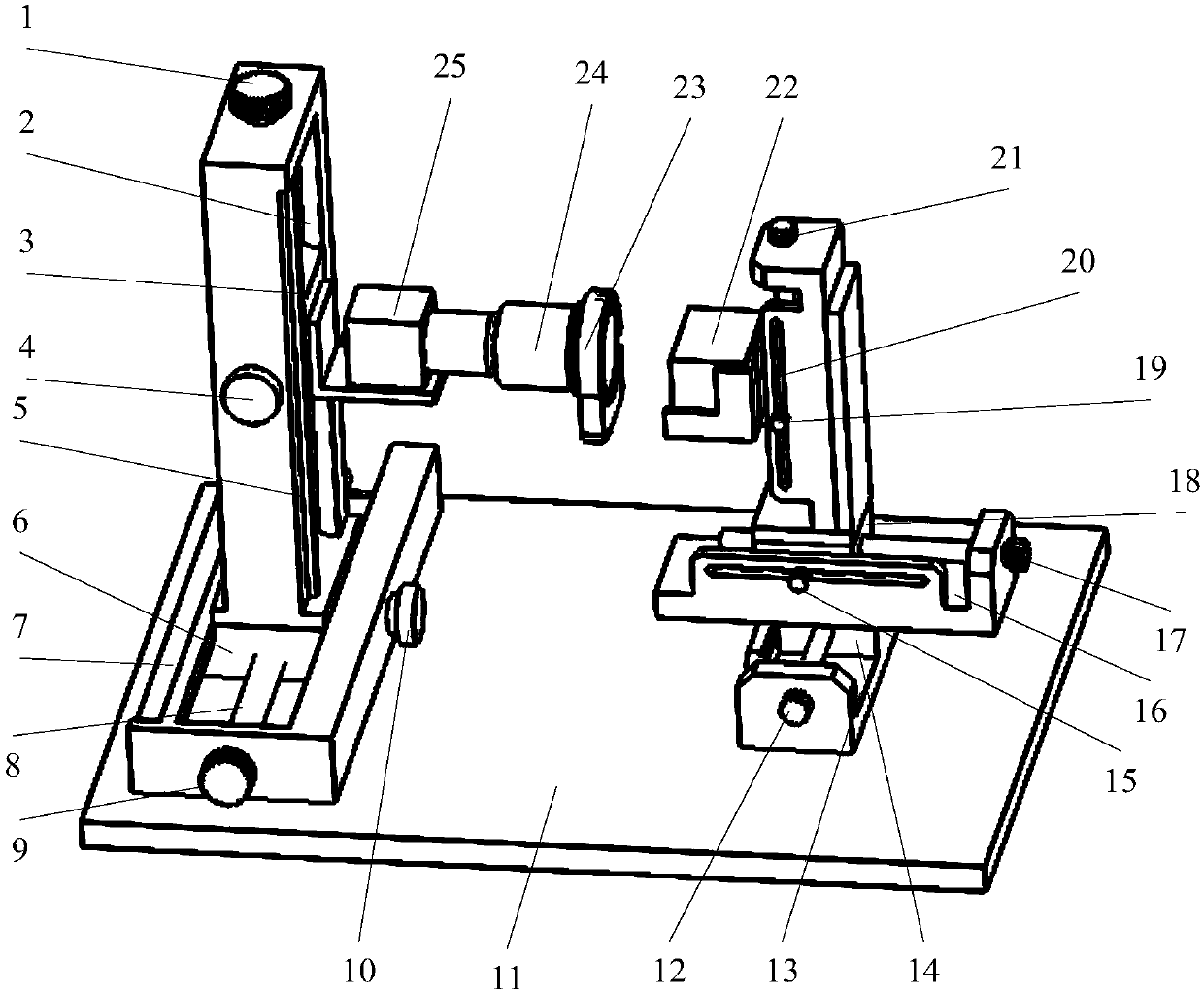
[0054] Such as figure 1 As shown, the online detection device for tool wear and damage based on CCD of the present invention includes a collection box 27, an industrial computer (not shown in the figure) and a display (not shown in the figure). Mainly be provided with CCD industrial camera 25, bi-telecentric lens 24, annular light source 23, prism 22 in collecting box 27, CCD industrial camera 25, bi-telecentric lens 24, industrial computer and display are connected successively.

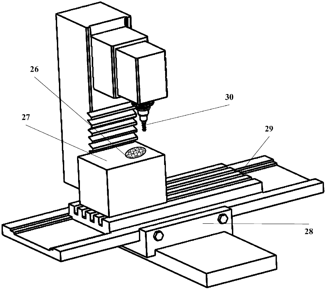
[0055] The collection box 27 is formed by setting a box body on the base 11. The box body includes four side box doors and a top box door. Each door can be opened. Brush mouth 26. The base 11 of the collection box 27 is provided with a camera lateral movement mechanism and a prism Y direction movement mechanism, the camera transverse movement mechanism is provided with a camera longitudinal movement mechanism, and the CCD industrial camera 25 is installed on the longitudinal slider 3 of the camera ...


PUM


Abstract

The invention discloses an online tool abrasion detection device based on CCD and a detection method of the online tool abrasion detection device. The device comprises a collection box, an industrialpersonal computer and a display. An industrial camera, a double telecentric lens, an annular light source and a triple prism are arranged in the collection box, and the industrial camera, the double telecentric lens, the industrial personal computer and the display are sequentially connected. The device detection method comprises the following steps that firstly, the whole device moves in the X-axis direction and the Y-axis direction of a machine tool; secondly, the whole device runs to the position below a tool, the tool descends, penetrates the collection box and stops at the position abovethe triple prism; fourthly, after calibration is finished, the industrial camera is fixed, and the triple prism is flush with the industrial camera; fifthly, all bottom blade images are collected at atime; sixthly, the height of the triple prism is adjusted, low-speed rotation is conducted, and side blade images are collected; and seventhly, the industrial personal computer conducts data processing on the collected blade part images. The online tool abrasion detection device is integrated to one camera, vision non-contact online detection is conducted, secondary clamping is avoided, and precision and efficiency are improved; and installation is convenient, and operation is simple.

Description

technical field [0001] The invention relates to a detection device and a detection method for accurately obtaining the wear length, width, area, etc. of a tool wear damage area on-line by a machine tool, and belongs to the technical field of tool wear damage detection. Background technique [0002] As a professional tool for CNC machine tools to process precision parts, the effective monitoring of its wear status can not only maximize the tool life potential, but also is an effective way to promote the development of intelligent manufacturing. Current tool wear and damage detection methods have certain limitations: [0003] First, the wear detection in industrial production is mainly judged by the experience of workers. Often the tool wear has exceeded the blunt standard, which affects the processing quality of the workpiece; or the tool is changed within a fixed time, but the wear does not reach the blunt standard. Tool change, resulting in tool waste; [0004] Second. In...

Claims


Application Information

Patent Timeline
IPC IPC(8): B23Q17/09B23Q17/24
CPCB23Q17/09B23Q17/0957B23Q17/2457Y02P70/10
Inventor 孙杰侯秋林孙颖国凯宋戈孙超
Owner SHANDONG UNIV
Why Eureka
Try Eureka