Gearbox lubricating system and lubricating oil flow control method of gearbox lubricating system

A lubricating system and lubricating oil technology, applied in the direction of gear lubrication/cooling, engine flow, lubricating parts, etc., can solve the problems of low intelligence and automation, less application of sensors, and inability to accurately control the opening size of the one-way valve. , to achieve the effect of convenient operation, high degree of intelligence, improved service life and degree of intelligence

Pending Publication Date: 2018-07-20
GUODIAN UNITED POWER TECH
View PDF2 Cites 11 Cited by
  • Summary
  • Abstract
  • Description
  • Claims
  • Application Information

AI Technical Summary

Problems solved by technology

The opening of the one-way valve is controlled by the viscosity and flow resistance of the lubricating oil. Although the service life of the one-way valve in this system is longer than that of the temperature-controlled valve, it is

Method used


Image

  • Gearbox lubricating system and lubricating oil flow control method of gearbox lubricating system
  • Gearbox lubricating system and lubricating oil flow control method of gearbox lubricating system
  • Gearbox lubricating system and lubricating oil flow control method of gearbox lubricating system

Examples


Embodiment Construction

[0036] This embodiment takes a gearbox lubrication system applied to a wind power generating set as an example to describe the technical solution of the application in detail, which should not be construed as any limitation to the application. The details are as follows.

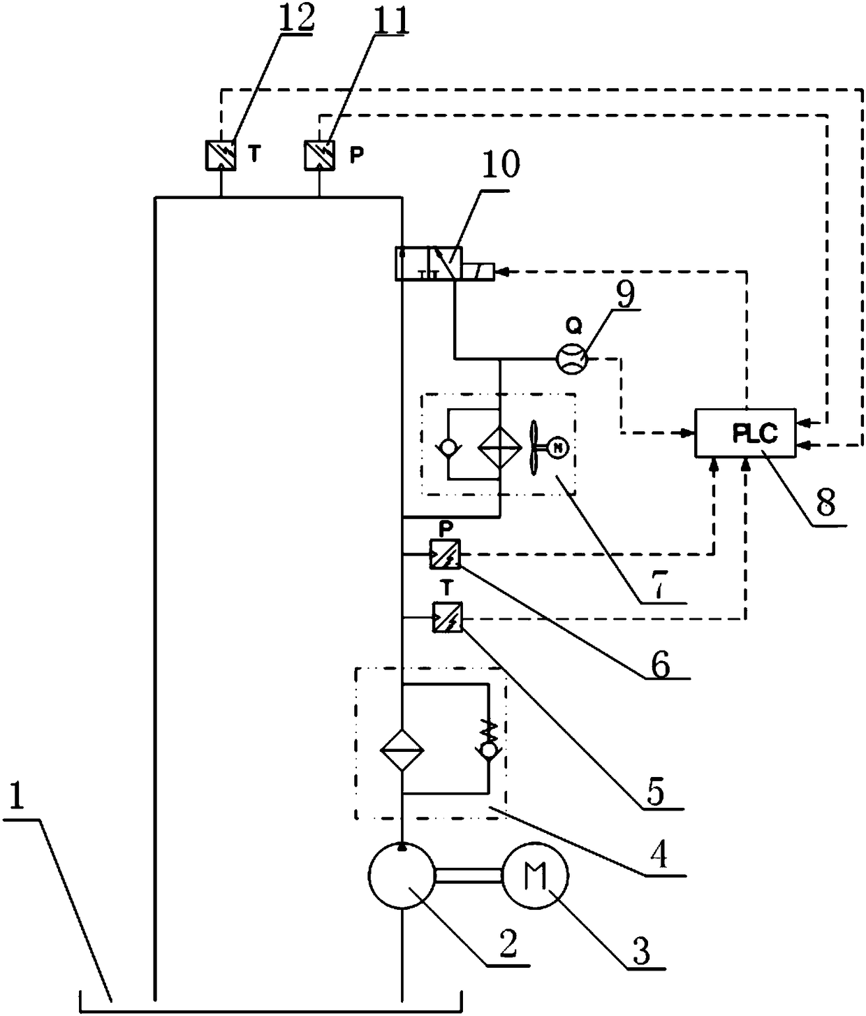
[0037] Refer to attached figure 1 As shown, the gearbox lubrication system of the wind power generating set in this embodiment includes a ring circuit formed by sequentially connecting the lubricating oil tank 1, the oil pump 2, the filter 4, the radiator 7 and the control valve, and the connection between the filter 4 and the control valve A straight-through passage is also provided, and the straight-through passage is arranged in parallel with the radiator 7 .

[0038] The control valve in this embodiment adopts an electronically controlled reversing valve 10 . Since the lubricating system is applied to the lubrication of the gearbox of the wind power generating set, the electronically controlled reversi...


PUM


Abstract

The invention discloses a gearbox lubricating system. The system comprises an annular loop which is sequentially connected with a lubricating oil tank, an oil pump, a radiator and an electric controlreversing valve, wherein a through passage is further arranged between the oil pump and the control valve, and the through passage is arranged in parallel with the radiator; the system further comprises a PLC main controller, a first temperature sensor, a second temperature sensor, a first temperature sensor and a second temperature sensor, wherein the first temperature sensor, the second temperature sensor, the first temperature sensor and the second temperature sensor are connected with the PLC main controller; the electric control reversing valve is connected with the PLC main controller, the control of an open precision of the electric control reversing valve is realized through the PLC main controller according to the monitoring data of the first temperature sensor, the second temperature sensor, the first temperature sensor and the second temperature sensor. The invention further discloses a lubricating oil flow control method of the gearbox lubricating system. According to the system and method, the PLC main controller is additionally arranged, the electric control reversing valve, the temperature sensors and pressure sensors are connected with the PLC main controller, wherein the service life and the precision control of the electric control reversing valve are relatively high, so that the service life and the intelligent control degree of the gear box lubricating system can be greatly improved.

Description

technical field [0001] The invention relates to the technical field of gearbox lubrication, in particular to a gearbox lubrication system and a lubricating oil flow control method thereof. Background technique [0002] The gearbox is an important part of the wind turbine. The gearbox lubrication system provides lubrication for the bearings and gears in the gearbox to reduce wear, and at the same time take away the heat generated during the operation of the gearbox. After the lubricating oil is cooled by the radiator, Return to the gearbox to continue to provide lubrication for the bearings and gears to ensure the normal operation of the gearbox. [0003] At present, most of the common gearbox lubrication systems use temperature control valves to control the flow of lubricating oil into the radiator, such as a utility model patent (application number 201720350576. The disclosed technical content is: a temperature control valve circuit is used to control the flow of lubricati...

Claims


Application Information

Patent Timeline
IPC IPC(8): F16H57/04F16N7/38F16N29/04F03D15/00F03D80/70
CPCF03D15/00F03D80/70F16H57/0413F16H57/0435F16N7/38F16N29/04F16N2210/025F16N2210/12F16N2210/14F16N2230/02F16N2250/04F16N2250/08F16N2250/40F16N2270/56Y02E10/72
Inventor 袁凌褚景春张建福潘磊李英昌孙黎周淑梅郭新毅
Owner GUODIAN UNITED POWER TECH
Why Eureka
Try Eureka