Electric melting device for full-automatic continuous feeding, deslagging, metal pouring and recovery

A melting device, fully automatic technology, applied in the direction of electric charge control, lighting and heating equipment, furnace components, etc., can solve the problems of large amount of flue gas, complicated tail gas treatment, high maintenance cost, etc., and achieve high heating efficiency, fast speed, The effect of convenient maintenance

Active Publication Date: 2018-07-20
上海煜工环保科技有限公司
View PDF5 Cites 3 Cited by
  • Summary
  • Abstract
  • Description
  • Claims
  • Application Information

AI Technical Summary

Problems solved by technology

The first kind of fuel combustion melting furnace is divided into surface combustion melting furnace, cyclone melting furnace, etc., its disadvantage is that it produces a large amount of smoke and the tail gas treatment is complicated
The second type of electric melting furnace is divided into resistance furnace, electric arc furnace, plasma furnace, etc. The disadvantages are large power consumption and high maintenance costs.

Method used


Image

  • Electric melting device for full-automatic continuous feeding, deslagging, metal pouring and recovery
  • Electric melting device for full-automatic continuous feeding, deslagging, metal pouring and recovery
  • Electric melting device for full-automatic continuous feeding, deslagging, metal pouring and recovery

Examples


Embodiment Construction

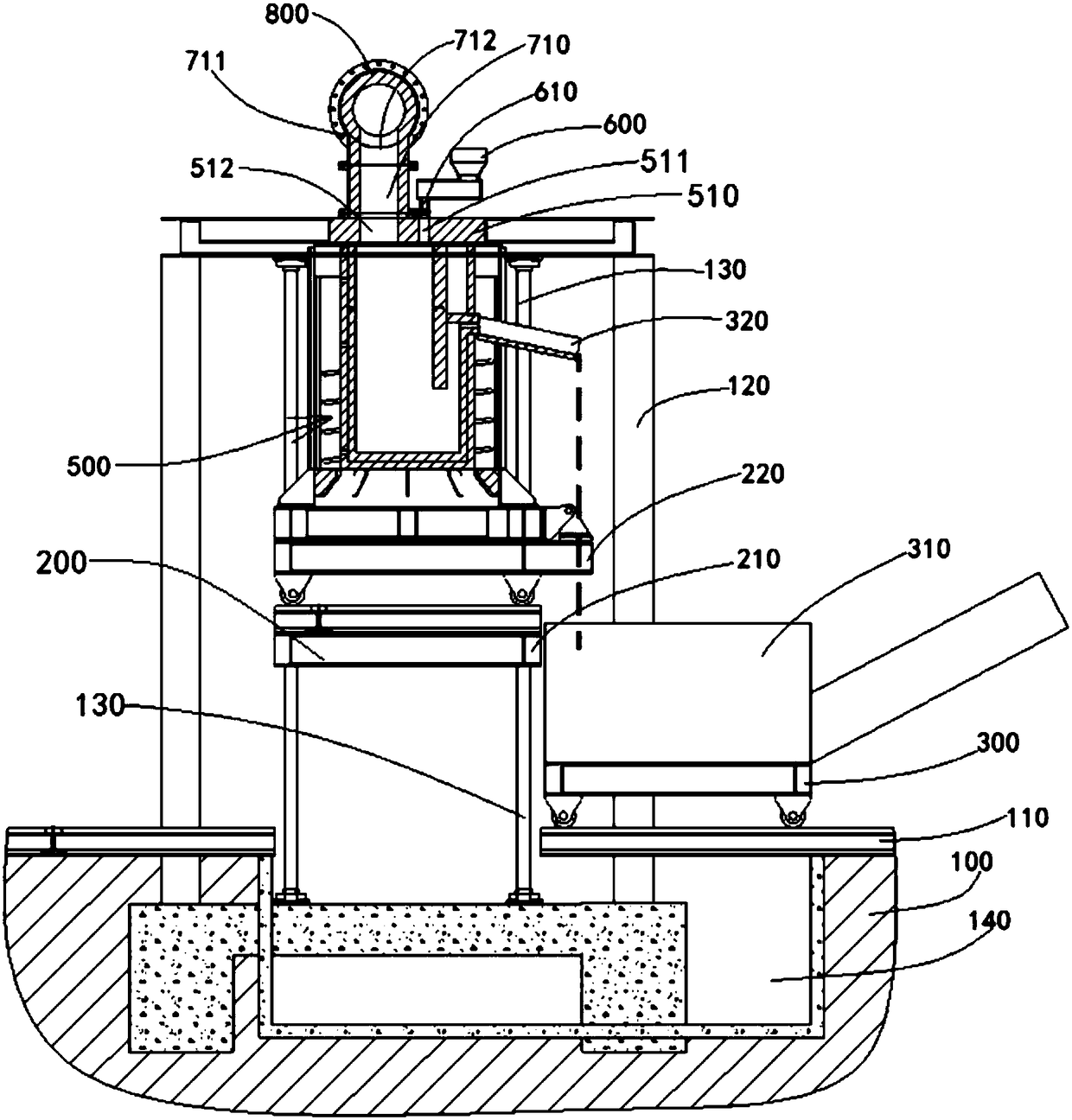
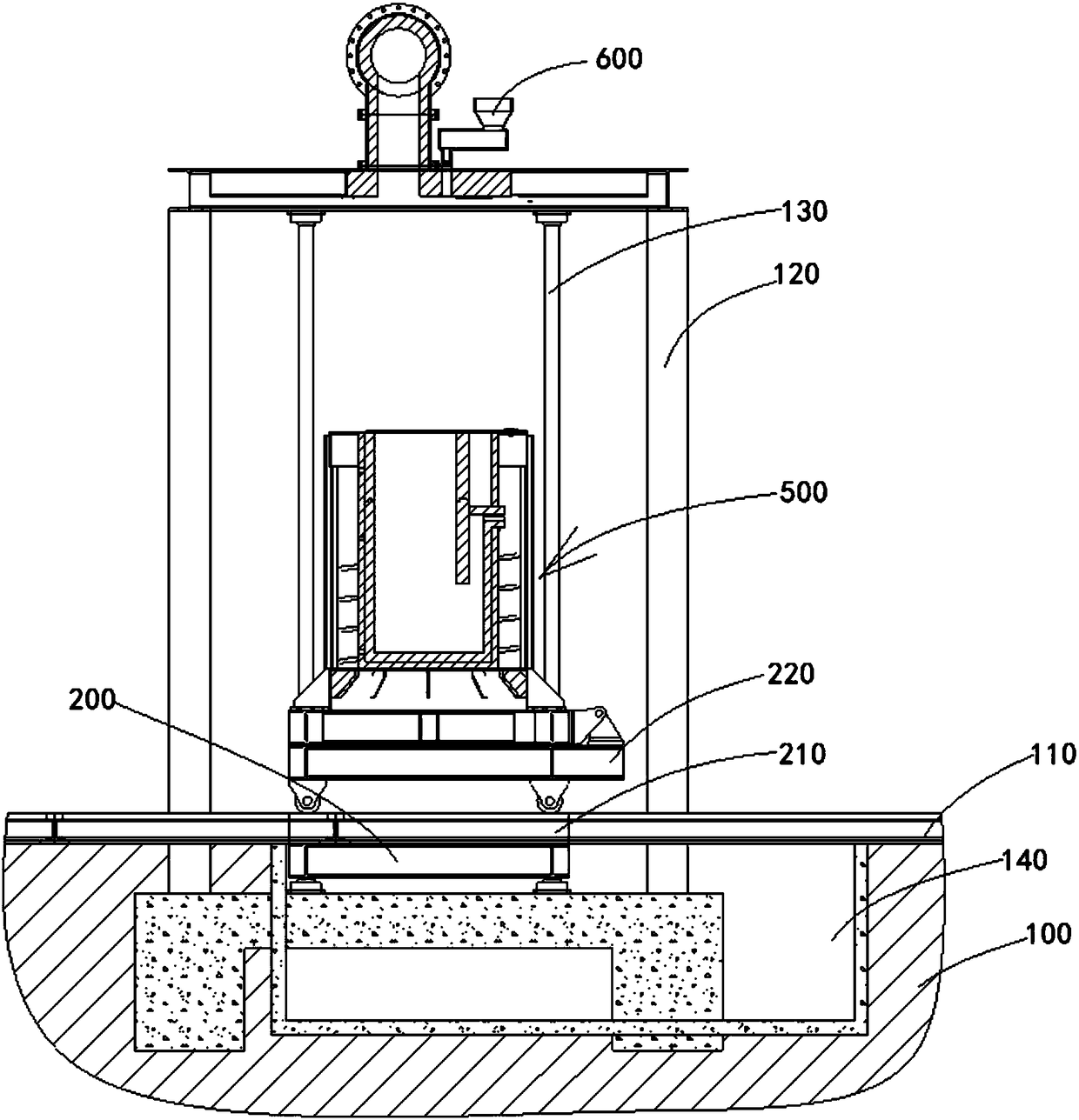
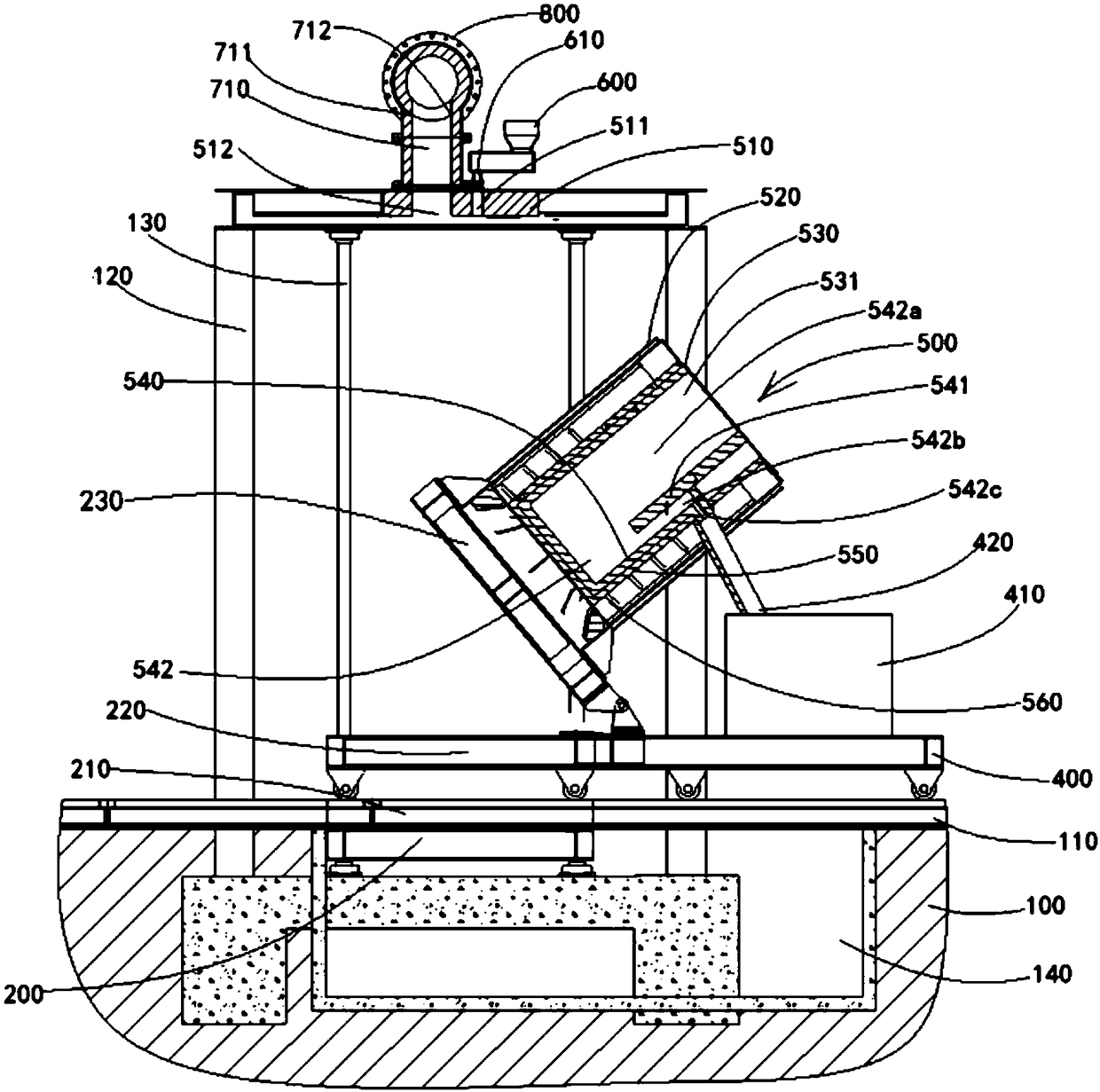
[0046] see Figure 1 to Figure 4 , the fully automatic continuous feeding slagging and dumping metal recovery electrofusion device shown in the figure includes a foundation 100 and a mechanical lifting platform 200 installed on the foundation 100, and a platform on the foundation surface of the foundation 100 and the mechanical lifting platform 200 A pair of parallel guide rails 110, 210 are laid on the surface, and the guide rail 210 on the platform surface of the mechanical lifting platform 200 is connected with the guide rail 110 on the base surface when the mechanical lifting platform 200 is lowered to the lowest position, so that the electric melting furnace can be moved Body 500, easy to repair and maintain.

[0047] On a pair of parallel guide rails 110, 210, a traveling trolley 220 for an electric melting furnace body, a traveling trolley 300 for a water-cooled slag extractor, and a traveling trolley 400 for a ladle are provided. Electric melting furnace body travelin...


PUM


Abstract

The invention discloses an electric melting device for full-automatic continuous feeding, deslagging, metal pouring and recovery. The device comprises of a foundation surface, a guide rail and a furnace cover support, wherein the foundation surface is paved on the foundation, the guide rail is laid on a mechanical lifting platform, and the furnace cover support is laid on the foundation surface ofthe foundation; an electric smelting furnace body travelling trolley, a water-cooled type slag discharging machine travelling trolley and a steel ladle travelling trolley are arranged on the guide rail; a water-cooled type slag discharging machine and a steel ladle are correspondingly arranged on the water-cooled type slag discharging machine travelling trolley and the steel ladle travelling trolley; the electric smelting furnace body traveling trolley is provided with an electric smelting furnace body hydraulic pressure pouring mechanism, when the electric smelting furnace body discharges molten steel, the molten steel are poured out by means of the electric smelting furnace body hydraulic pressure pouring mechanism; and a furnace cover and a vibration type feeder are installed on the furnace cover support, wherein a feeding hole and a smoke outlet are formed in the furnace cover, a discharging hole in the vibration feeding machine is in butt joint with a feeding hole in the furnacecover, in the molten state, the electric smelting furnace body is located below the furnace cover, and the furnace cover covers a furnace opening of the electric smelting furnace body.

Description

technical field [0001] The invention relates to the technical field of an electric heating and melting device for high-temperature melting treatment of dried, crushed and formed waste containing heavy metals to make it harmless, volume reduction and resource utilization, and energy saving, in particular to a fully automatic continuous feeding Slagging and dumping metal recovery electro-smelting device. Background technique [0002] At present, there are two types of representative melting furnaces on the market: the first type is a fuel-burning melting furnace, and the second type is an electric melting furnace. The first kind of fuel combustion melting furnace is divided into surface combustion melting furnace, cyclone melting furnace, etc., and its disadvantage is that it produces a large amount of smoke and the tail gas treatment is complicated. The second type of electric melting furnace is divided into resistance furnace, electric arc furnace, plasma furnace, etc. The ...

Claims


Application Information

Patent Timeline
Patent Type & Authority Applications(China)
IPC IPC(8): F27D3/15C22B7/00
CPCC22B7/003F27D3/159Y02P10/20
Inventor 丁玉静丁宝太刘诚晨
Owner 上海煜工环保科技有限公司
Why Eureka
Try Eureka