
Primary formation lamination machine of battery cell of lithium battery

A lamination machine, lithium battery technology, applied in the direction of secondary batteries, circuits, electrical components, etc., can solve the problems of bad pole pieces, impossible pole piece one-time lamination, easy to scratch pole pieces, etc., to achieve easy storage and take, improve lamination efficiency, increase the effect of adaptability

Pending Publication Date: 2018-07-20
HEBEI UNIV OF TECH +1
View PDF1 Cites 11 Cited by
  • Summary
  • Abstract
  • Description
  • Claims
  • Application Information

AI Technical Summary

Problems solved by technology

[0003] The application number is 201611243940.9, which discloses a laminate machine. The loading module of the laminate machine adopts a rotary station, which divides the operation completed by one station in the prior art into multiple stations, which improves the efficiency of chip placement. , but its rotating station is limited, and the lamination also needs to be completed many times. It is impossible to realize the one-time lamination of the pole piece. Compared with the traditional lamination machine, the lamination efficiency is not greatly improved.
[0004] At present, the traditional stacking machine needs to attach the positive and negative electrodes many times, which makes the lithium battery stacking processing efficiency not high, and the cost of the equipment is high. In addition, the stacking claws are easy to scratch the poles during the stacking process. Lead to poor pole piece, low reliability

Method used


Image

  • Primary formation lamination machine of battery cell of lithium battery
  • Primary formation lamination machine of battery cell of lithium battery
  • Primary formation lamination machine of battery cell of lithium battery

Examples


Embodiment Construction

[0049] Specific examples of the present invention are given below. The specific embodiments are only used to further describe the present invention in detail, and do not limit the protection scope of the claims of the present application.

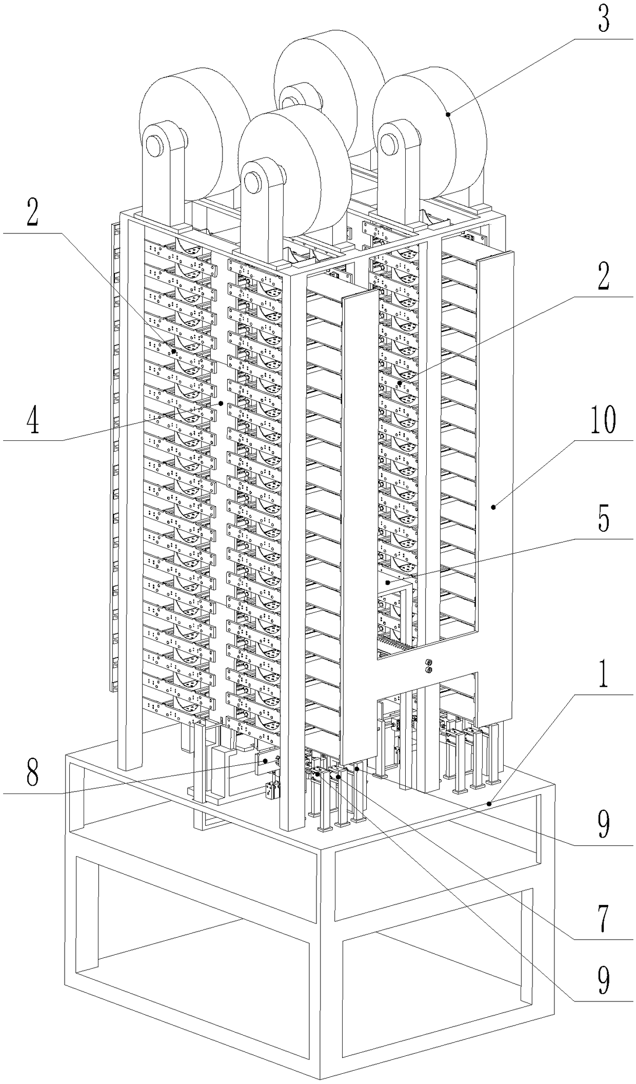
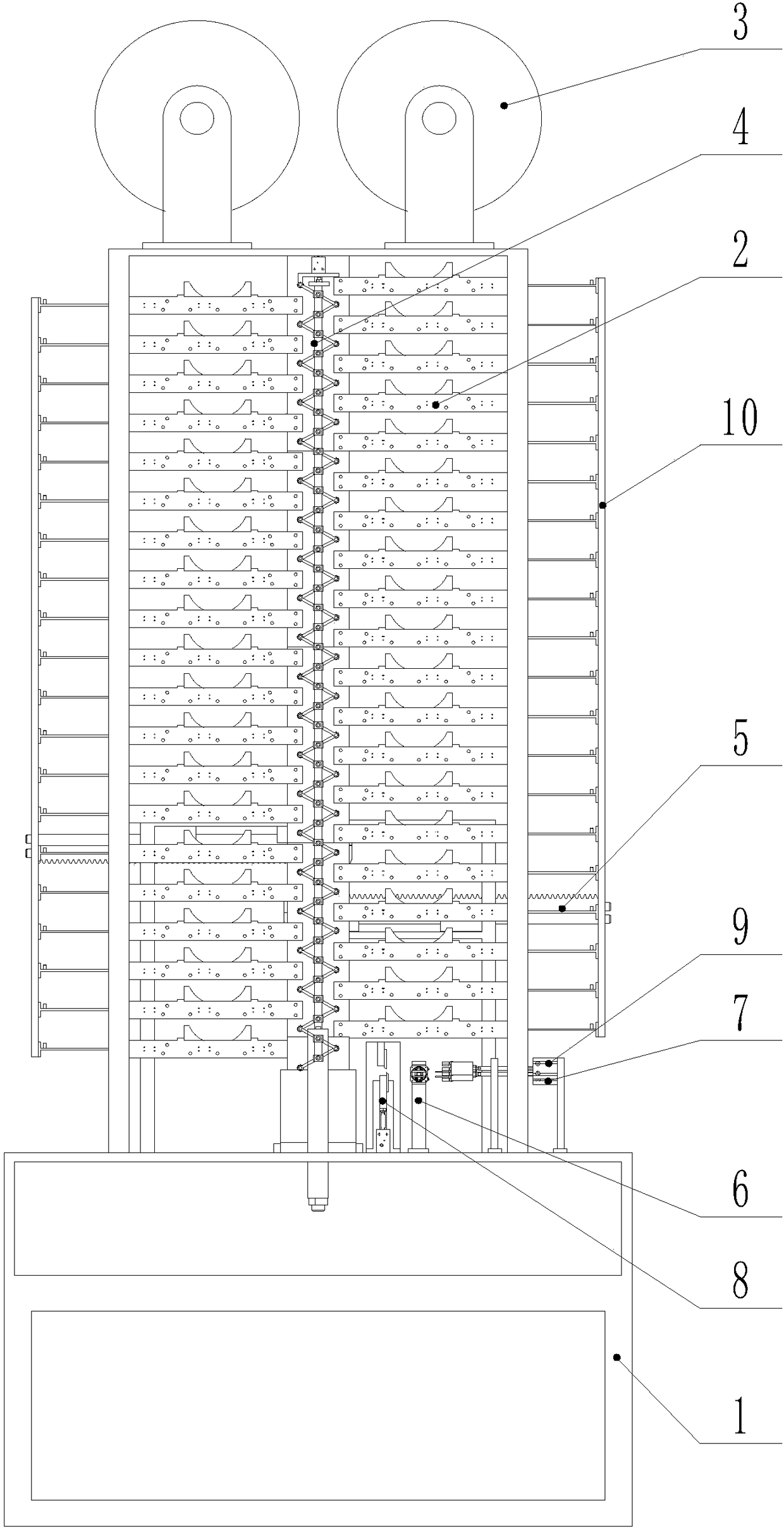
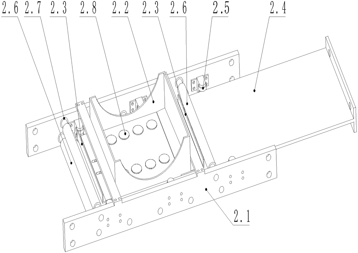
[0050] The invention provides a lithium battery cell one-time forming stacking machine (see Figure 1-9 , referred to as stacking machine), including frame 1, diaphragm unwinding mechanism 3, diaphragm winding mechanism 6, cell clamping mechanism 7, diaphragm clamping mechanism 9 and connecting plate 10; it is characterized in that the stacking machine also includes Electrode conveying mechanism 2, stacking mechanism 4, transmission mechanism 5 and diaphragm cutting mechanism 8;

[0051] The stacking mechanism 4 is installed in the middle of the frame 1, and is used for one-time stacking assembly of the positive and negative pole pieces and the diaphragm to form a battery cell;

[0052] The pole piece conveying mechanism 2 is two groups w...


PUM


Abstract

The invention discloses a primary formation lamination machine of a battery cell of a lithium battery. The primary formation lamination machine comprises a rack, a separator unwinding mechanism, a separator winding mechanism, a battery cell clamping mechanism, a separator clamping mechanism, a connection plate, a pole plate transmission mechanism, a lamination mechanism, a transmission mechanism and a separator cutting mechanism, wherein the lamination mechanism is used for performing primary lamination assembly on a positive pole plate, a negative pole plate and a separator, the pole plate transmission mechanism is used for transmitting the positive pole plate and the negative pole plate, the separator unwinding mechanism is used for placing the separator between the positive pole plate and the negative pole plate, the transmission mechanism is used for providing power for the pole plate transmission mechanism, the separator winding mechanism is used for performing separator coating on the battery cell formed by the lamination mechanism, the battery cell clamping mechanism is used for clamping the battery cell before and after separator coating, the separator cutting mechanism isused for cutting the separator after separator coating is completed, and the separator clamping mechanism is used for transmitting the separator to a clamp at the bottom of the lamination mechanism. By the lamination machine, primary lamination formation of the positive pole plate and the negative pole plate is achieved, and the lamination efficiency is greatly improved.

Description

technical field [0001] The invention relates to the field of lithium battery manufacturing, in particular to a one-time forming lamination machine for lithium battery cells. Background technique [0002] The internal structure of a lithium battery includes sequentially stacked positive electrode sheets and negative electrode sheets, and the positive and negative electrode sheets are separated by a separator. The stacking machine is mainly used in the stacking process of lithium battery cells, and its stacking methods are divided into two types: rotary type and reciprocating type. Rotary stacks are characterized by application to small battery stacks, and reciprocating stacks are characterized by large battery stacks. Laminating machine is generally composed of the following mechanisms: feeding mechanism, positive electrode material box, negative electrode material box, positive electrode secondary positioning mechanism, negative electrode secondary positioning mechanism, po...

Claims


Application Information

Patent Timeline
IPC IPC(8): H01M10/0583
CPCH01M10/0583Y02E60/10Y02P70/50
Inventor 关玉明李祥利弓波肖艳军殷子琪葛浩吴锡杨培
Owner HEBEI UNIV OF TECH
Learn More