Eureka AIR delivers breakthrough ideas for toughest innovation challenges, trusted by R&D personnel around the world.

Double-crankshaft type sewage compression and dehydration environmental-friendly treatment device

A sludge compression and environmental protection treatment technology, applied in the direction of water/sludge/sewage treatment, sludge treatment, dehydration/drying/thickened sludge treatment, etc., can solve the problem of sludge filter press damage and sludge plugging Problems such as mud mouth and large volume can be solved, and the effect of increasing efficiency, high reliability and reasonable structure can be achieved

Inactive Publication Date: 2018-07-24
合肥净龙环保科技有限公司
View PDF5 Cites 4 Cited by
  • Summary
  • Abstract
  • Description
  • Claims
  • Application Information

AI Technical Summary

Problems solved by technology

[0003] Sewage will produce a large amount of sludge after sedimentation treatment. Even after concentration and digestion treatment, the water content is still as high as 96%. Generally, large and medium-sized sewage treatment plants use mechanical dehydration, but during the process of sludge press dewatering, sludge may be blocked at the outlet of the machine, which not only affects the sludge press dehydration The progress of the work can also cause damage to the sludge filter press

Method used

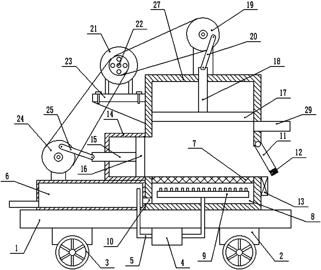
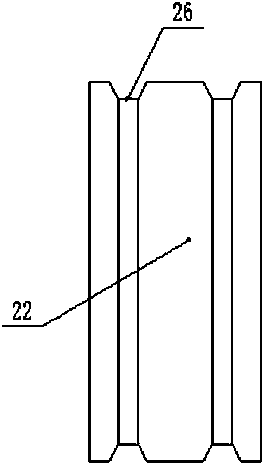
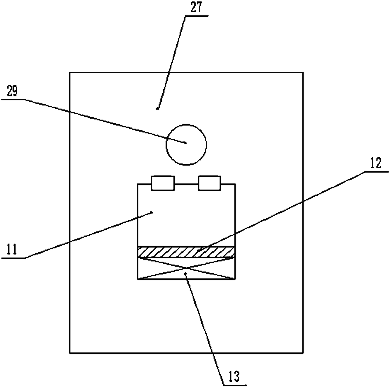

Image

  • Double-crankshaft type sewage compression and dehydration environmental-friendly treatment device
  • Double-crankshaft type sewage compression and dehydration environmental-friendly treatment device
  • Double-crankshaft type sewage compression and dehydration environmental-friendly treatment device

Examples


Embodiment Construction

[0022] It should be noted that, in the case of no conflict, the embodiments of the present invention and the features in the embodiments can be combined with each other.

[0023] In describing the present invention, it should be understood that the terms "center", "longitudinal", "transverse", "upper", "lower", "front", "rear", "left", "right", " The orientations or positional relationships indicated by "vertical", "horizontal", "top", "bottom", "inner" and "outer" are based on the orientations or positional relationships shown in the drawings, and are only for the convenience of describing the present invention and Simplified descriptions, rather than indicating or implying that the device or element referred to must have a particular orientation, be constructed and operate in a particular orientation, and thus should not be construed as limiting the invention. In addition, the terms "first", "second", etc. are used for descriptive purposes only, and should not be understood ...


PUM


Abstract

The invention discloses a double-crankshaft type sewage compression and dehydration environmental-friendly treatment device which comprises a base, wherein a dehydration bucket is mounted on the rightside of the upper end of the base; a pressing plate is mounted inside the upper end of the dehydration bucket; a lifting shaft is connected with the middle part of the upper end of the pressing plate; a dehydration plate is mounted in the middle of the dehydration bucket; a washing cavity is formed inside the area of the dehydration bucket at the lower end of the dehydration plate; a water storage tank is mounted on the left side of the upper end of the base; a water guide pump is mounted in the middle of the lower end of the base; a motor base is mounted at the upper end of the dehydration bucket; a driving motor is connected with the upper end of the motor base; a driving belt wheel is connected in the middle of the front end of the driving motor; a first rotating wheel is connected with the middle of the upper end of the dehydration bucket through a support rack; a first crankshaft is connected with the middle of the first rotating wheel; a second rotating wheel is connected with the upper end of the water storage tank through the support rack; a second crankshaft is connected with the middle of the second rotating wheel. By adopting the device, up and down lifting of the pressing plate and left and right movement of the push plate can be achieved, furthermore sludge can be compressed and dehydrated and discharged in time, and the situation that a discharge hole is blockedby compressed sludge blocks can be avoided.

Description

technical field [0001] The invention relates to the technical field of environmental protection equipment, in particular to a double crank type sludge compression dehydration environmental protection treatment device. Background technique [0002] Sludge refers to the precipitated sludge, particulate matter and floating matter produced when wastewater is treated by physical, chemical, physical-chemical and biological methods. Sludge generally refers to thick matter between liquid and solid, which can be transported by pump, but it is difficult to separate solid and liquid by sedimentation. The concentration of suspended solids is generally 1% to 10%, and the concentration below this level is often called mud. Due to the different sources of sludge and different water treatment methods, the properties of the generated sludge are different, and there are many types of sludge. According to the source, the sludge mainly includes domestic sewage sludge, industrial wastewater slu...

Claims


Application Information

Patent Timeline
Patent Type & Authority Applications(China)
IPC IPC(8): C02F11/12
CPCC02F11/122
Inventor 陈薇
Owner 合肥净龙环保科技有限公司
Why Eureka
Eureka Blog
Learn More