Control device for internal combustion engine

A control device and internal combustion engine technology, applied in engine control, internal combustion piston engine, electrical control, etc., can solve the problem of slowing down of throttle valve closing speed

Inactive Publication Date: 2018-07-24
HONDA MOTOR CO LTD
View PDF13 Cites 0 Cited by
  • Summary
  • Abstract
  • Description
  • Claims
  • Application Information

AI Technical Summary

Problems solved by technology

[0002] Patent Document 1 discloses a control device for reducing the valve closing speed of the throttle valve when the deceleration operation is performed

Method used


Image

  • Control device for internal combustion engine
  • Control device for internal combustion engine
  • Control device for internal combustion engine

Examples


Embodiment Construction

[0042] Embodiments of the present invention will be described below with reference to the drawings.

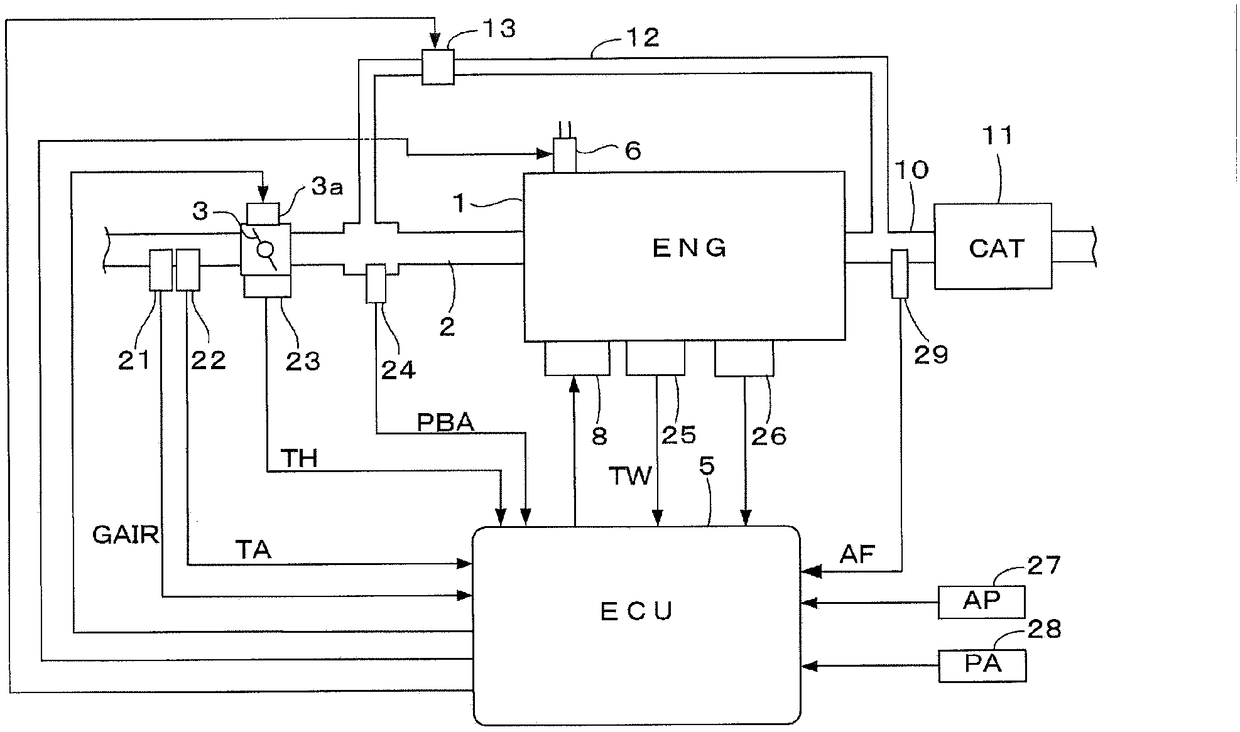
[0043] figure 1It is a diagram showing the structure of an internal combustion engine and its control device according to an embodiment of the present invention. The internal combustion engine (hereinafter referred to as "engine") 1 shown in the figure has, for example, four cylinders, and a direct combustion engine is provided in each cylinder. Injector 6 for injecting fuel in the chamber. The operation of the injector 6 is controlled by an electronic control unit (hereinafter referred to as “ECU”) 5 . In addition, a spark plug 8 is attached to each cylinder of the engine 1 , and the ignition timing of the spark plug 8 is controlled by the ECU 5 . A throttle valve 3 is arranged on an intake passage 2 of the engine 1 .

[0044] The following components are connected to the ECU5: the intake air flow sensor 21, which detects the intake air flow GAIR of the engine 1; the intak...


PUM


Abstract

The present invention provides a control device for an internal combustion engine, being able to suppress engine misfire by appropriately controlling the ignition period when the engine deceleration is performed in a state that the exhaust gas recirculation rate is high. When the exhaust gas recirculation rate exceeds the combustion instability threshold and the estimated filling efficiency indicating the engine load is less than the specific retard control threshold, the ignition period is configured to be the specific retard limit control at a specific ignition period of a retard corner side, compared with the optimal ignition period by taking a compression stroke end period as the retard limit. In the compression stroke, the temperature of the in-cylinder gas rises due to compression. Therefore, by taking compression stroke end period as the retard limit, the ignition is performed at a specific ignition period at the retard corner side, compared with the optimal ignition period, andstable ignition and suppression of engine misfire can be performed, compared with the situation that ignition is performed at the optimal ignition period.

Description

technical field [0001] The present invention relates to a control device for an internal combustion engine provided with an exhaust gas recirculation device, and more particularly to a control device for controlling when the internal combustion engine is decelerated while the exhaust gas recirculation rate is high. Background technique [0002] Patent Document 1 discloses a control device for reducing the valve closing speed of a throttle valve when a deceleration operation is performed with exhaust gas recirculation performed in an internal combustion engine including an exhaust gas recirculation device and a supercharger. Through this control, it is possible to prevent the occurrence of engine misfire due to insufficient intake air due to the influence of recirculated exhaust gas remaining in the intake passage. [0003] Patent Document 2 discloses an ignition timing control device that controls the ignition timing based on the exhaust gas recirculation rate. According to...

Claims


Application Information

Patent Timeline
IPC IPC(8): F02D43/00
CPCF02D37/02F02D41/0062F02D41/0072F02P5/045F02P5/1516F02D41/0047F02D41/18F02D2200/0402F02D2200/0404F02D2200/0406F02D2200/10Y02T10/40F02D41/1444F02P5/15
Inventor 上野将树木村范孝伊原光祐
Owner HONDA MOTOR CO LTD
Why Eureka
Try Eureka