Bearing state online monitoring system and method based on optical fiber vibration sensing
A monitoring system, optical fiber vibration technology, applied in the direction of mechanical bearing testing, etc., can solve the problems of increasing system cost, laser loss, etc., to achieve good sensitivity, reduce power, and reduce costs
- Summary
- Abstract
- Description
- Claims
- Application Information
AI Technical Summary
Problems solved by technology
Method used
Image

Examples
Embodiment Construction
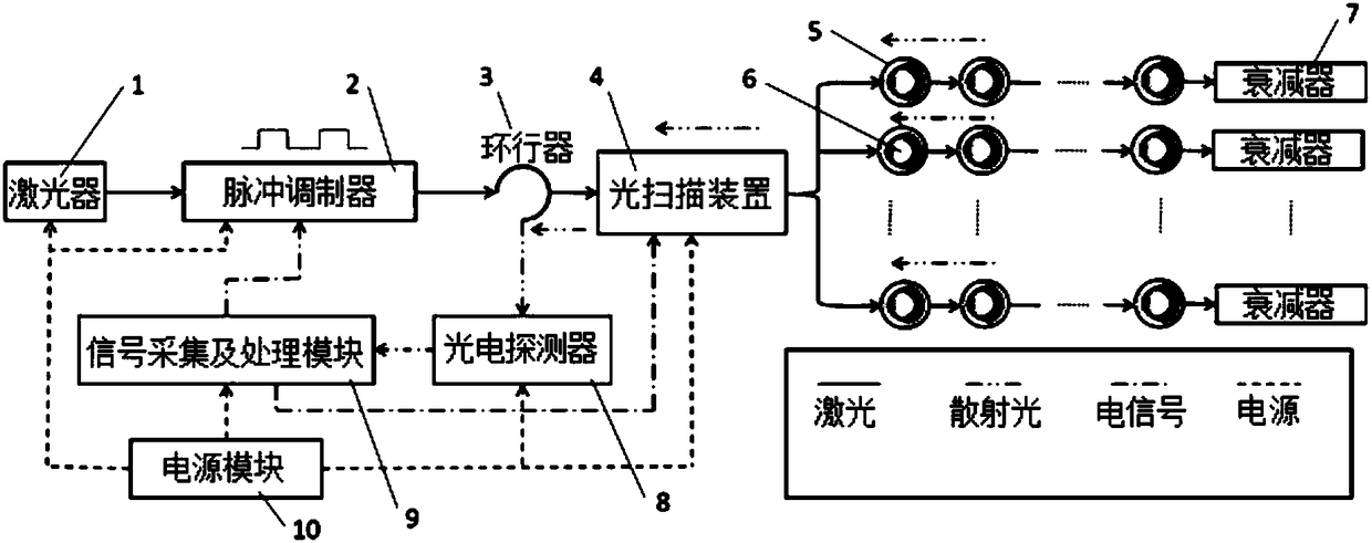
[0038] refer to figure 1 , an on-line monitoring system for bearing status based on optical fiber vibration sensing (hereinafter, sometimes simply referred to as "monitoring system") according to an embodiment of the present invention includes a laser 1, a pulse modulator 2, a circulator 3, an optical scanning device 4, a vibration Sensing optical cable 5 , attenuator 7 , photodetector 8 , signal acquisition and processing module 9 and power module 10 .
[0039] After the laser light produced by the laser 1 is modulated into pulsed laser light by the pulse modulator 2, it enters a vibration sensing optical cable 5 among a plurality of (n) vibration sensing optical cables 5 through a circulator 3 and an optical scanning device 4 to detect multiple ( m) the vibration of the bearing 6 under working conditions. The vibration of the bearing 6 will cause the stress of the optical fiber in the vibration sensing optical cable 5 to change, thereby causing the corresponding change of t...
PUM
 Abstract
Description
Claims
Application Information
PatSnap Eureka turns technology decisions into work you can execute. Powered by our Innovation Knowledge Graph, it runs expert workflows across engineering, life sciences, materials and intellectual property. Get your review-ready output in minutes.


