
Humidity holding mechanism prior to cleaning of silicon wafer

A technology for maintaining mechanism and silicon wafer cleaning, which is applied in the direction of electrical components, semiconductor/solid-state device manufacturing, circuits, etc. It can solve problems such as uncleanness, difficult cleaning of impurities, and poor silicon wafers, so as to achieve the effect of ensuring the yield rate

Pending Publication Date: 2018-07-24
苏州卓樱自动化设备有限公司
View PDF0 Cites 0 Cited by
  • Summary
  • Abstract
  • Description
  • Claims
  • Application Information

AI Technical Summary

Problems solved by technology

[0002] There are a lot of impurities attached to the surface of the silicon wafer before it enters the washing machine. If the washing machine or the inserting machine fails and is shut down for maintenance, the silicon wafers on the inserting machine and in the feeding trough of the washing machine will be exposed for a long time, waiting for the moisture on the surface of the silicon wafer. After the volatilization, the impurities will adhere to the surface of the silicon wafer, and then the surface impurities are difficult to clean or not clean after being cleaned by the washing machine, which will eventually lead to defective silicon wafers

Method used


Image

  • Humidity holding mechanism prior to cleaning of silicon wafer
  • Humidity holding mechanism prior to cleaning of silicon wafer

Examples


Embodiment Construction

[0016] Specific embodiments of the present invention will be described in detail below in conjunction with the accompanying drawings.

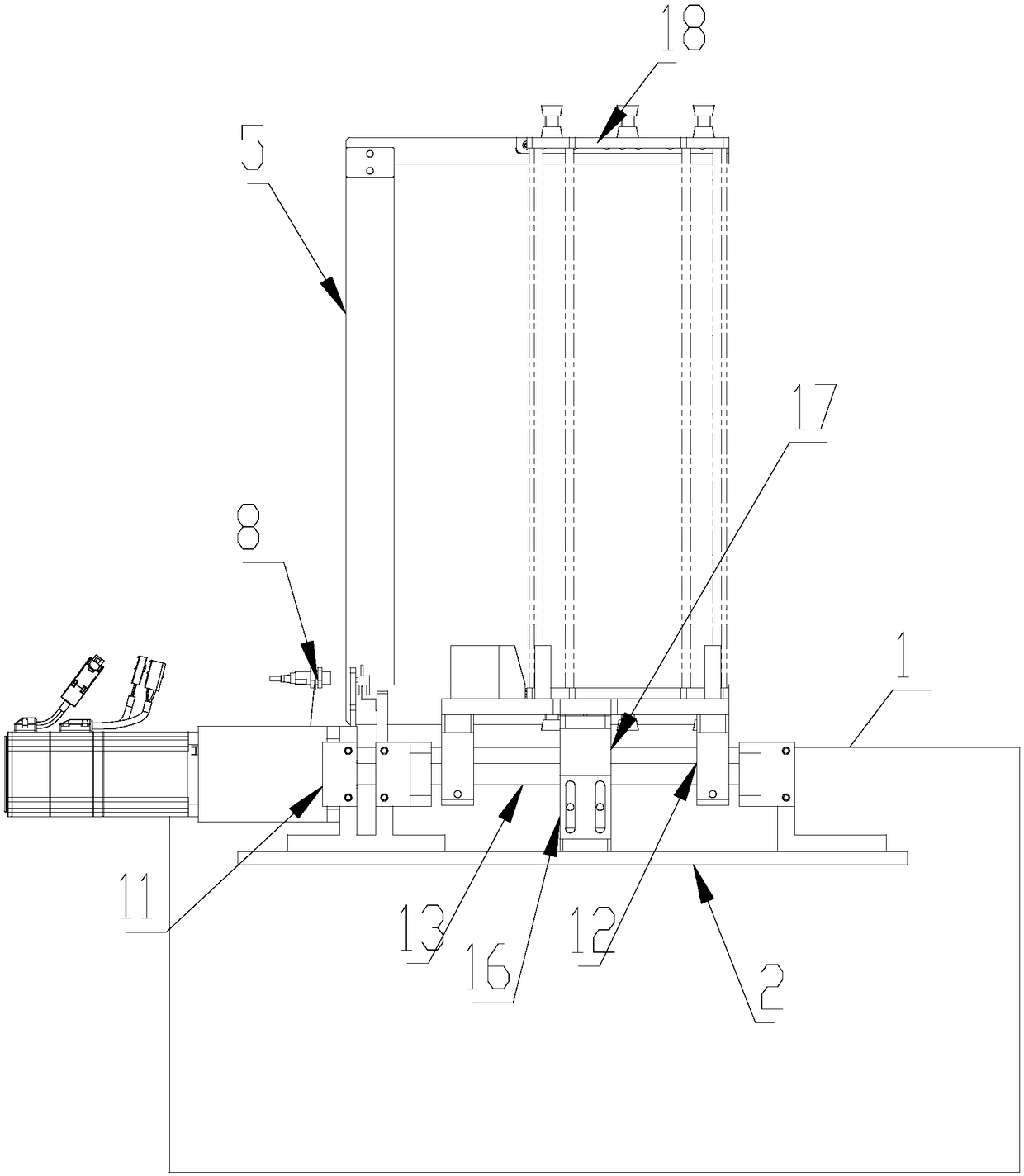
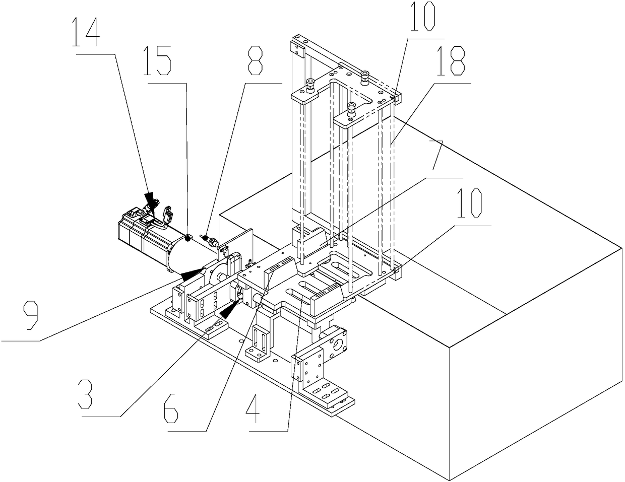
[0017] Such as Figure 1-2 As shown, a humidity maintaining mechanism before silicon wafer cleaning includes a water tank 1 and a mounting base 2 beside the water tank 1. The mounting base 2 is provided with a rotating base 3 and a power device for driving the rotating base to rotate 90 degrees. The first bearing seat 11 and the second bearing seat 12 are arranged on the mounting seat 2, and the rotating shaft 13 is provided on the said rotating seat 3, and the rotating shaft 13 passes through the first bearing seat 11 and the second bearing seat 12 to be connected with the power unit. connect. The power device includes a servo motor 14 and a reducer 15 connected together, and the output shaft of the reducer 15 is connected with the rotating shaft 13 .

[0018] The upper edge of the rotating seat 3 is higher than the upper edge of the water ...


PUM


Abstract

The present invention discloses a humidity holding mechanism prior to cleaning of a silicon wafer. The humidity holding mechanism comprises a water channel and a mounting seat located beside the waterchannel, the mounting seat is provided with a rotation seat and a power device driving 90-degree rotation of the rotation seat, an upper edge of the rotation seat is higher than an upper edge of thewater channel and is located in an area of the water channel after 90-degree rotation of the rotation seat, the upper edge of the rotation seat is provided with a flower basket location plate, one side, close to the water channel, on the flower basket location plate is provided with a retainer rack pushed and butted against a side of a silicon wafer flower basket, the retainer rack supports the whole silicon wafer flower basket to be immersed in the water channel after 90-degree rotation of the rotation seat, two end portion location blocks configured to limit the position of the silicon waferflower basket are arranged at a position, opposite to the retainer rack, on the flower basket location plate, a side location block configured to locate the other side of the silicon wafer flower basket is arranged between the two end portion location blocks and the retainer rack, the rotation seat is provided with a detection block, a first detection switch cooperative with the detection deviceis arranged at the initial position of the rotation seat on the mounting seat, and a second detection switch cooperative with the detection block is arranged at a termination position of the rotationseat on the mounting seat.

Description

technical field [0001] The invention relates to a silicon wafer processing equipment, in particular to a humidity maintaining mechanism before the silicon wafer is cleaned. Background technique [0002] There are a lot of impurities attached to the surface of the silicon wafer before it enters the washing machine. If the washing machine or the inserting machine fails and is shut down for maintenance, the silicon wafers on the inserting machine and in the feeding trough of the washing machine will be exposed for a long time, waiting for the moisture on the surface of the silicon wafer. After the volatilization, the impurities will adhere to the surface of the silicon wafer, and then the surface impurities are difficult to clean or not clean after being cleaned by the washing machine, which will eventually lead to defective silicon wafers. Contents of the invention [0003] The technical problem to be solved by the present invention is to provide a humidity maintaining mecha...

Claims


Application Information

Patent Timeline
Patent Type & Authority Applications(China)
IPC IPC(8): H01L21/67H01L21/68H01L21/66
CPCH01L21/67011H01L21/68H01L22/12Y02P70/50
Inventor 唐亚忠
Owner 苏州卓樱自动化设备有限公司
Learn More