Voltage source inverter common-mode voltage inhibition method

A voltage source inverter and common-mode voltage technology, which is applied in photovoltaic power generation, electrical components, and conversion of AC power input to DC power output.

Active Publication Date: 2018-07-24
ANHUI UNIVERSITY
View PDF6 Cites 2 Cited by
  • Summary
  • Abstract
  • Description
  • Claims
  • Application Information

AI Technical Summary

Problems solved by technology

Although the literature "Yan Xueli, Hao Benang, Xia Zitian, et al. Analysis of common-mode voltage suppression strategy based on predictive control [J]. Coal Mine Electromechanical, 2014, (5): 58-64." and the literature "Sung-ki Mun, Sangshin Kwak. Reducing Common-Mode Voltage of Three-Phase VSIs using the Predictive Current Control Method based on ReferenceVoltage[J].Journal of Power Electronics,2015,15(3):712-720.Sung-ki Mun,Sangshin Kwak. Voltage predictive current control method to reduce common-mode voltage of three-phase voltage source inverter [J]. Power Electronics Journal, 2015, 15(3): 712-720.", Chinese Patent "A Permanent Magnet Synchronous Motor Model-predicted common-mode voltage suppression method (201510724306.6)" studies the model-predicted common-mode voltage suppression method of voltage source inverter based on model predictive control, but these methods do not consider the influence of dead zone on common-mode voltage, which leads to common-mode The voltage still has a large voltage spike

Method used


Image

  • Voltage source inverter common-mode voltage inhibition method
  • Voltage source inverter common-mode voltage inhibition method
  • Voltage source inverter common-mode voltage inhibition method

Examples


Embodiment Construction

[0063] The following describes the implementation of the method in detail.

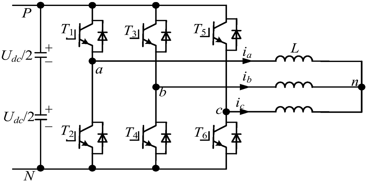
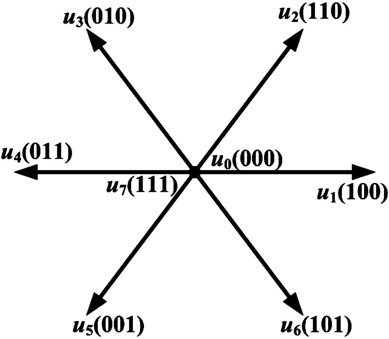
[0064] First, the method is applied to figure 1 In the voltage source inverter shown, the a-phase power switch tube T 1 Turn on T 2 When shutting down, S a = 1;T 1 Turn off T 2 When turned on, S a = 0; similarly, the b-phase power switch tube T 3 Turn on T 4 When shutting down, S b = 1;T 3 Turn off T 4 When turned on, S b =0; c-phase power switch tube T 5 Turn on T 6 When shutting down, S c = 1; T 5 Turn off T 6 When turned on, S c =0. The corresponding 8 voltage vectors such as figure 2 shown, denoted as u(S a S b S c ), all 8 vectors are denoted as u 0 (000), u 1 (100), u 2 (110), u 3 (010), u 4 (011), u 5 (001), u 6 (101) and u 7 (111).

[0065] The present invention is realized through the following steps:

[0066]Step 1. Sampling the three-phase current i of the voltage source inverter a i b i c , and get the current i through coordinate transformation α i β ,...


PUM


Abstract

The invention discloses a voltage source inverter common-mode voltage inhibition method, and belongs to the power electronic technical field; the method comprises the following steps: selecting a backup voltage vector for each control cycle according to a voltage vector of the previous cycle and a sector to which the current vector of the present cycle is located, and optimizing a target functionaccording to the backup voltage vector, thus obtaining the optimal voltage vector of the present cycle; applying the optimal voltage vector on an inverter. The method can fully consider the influenceson the common-mode voltage by a dead zone when the backup voltage vector is selected, thus fully overcoming the dead zone influences. Therefore, the method is applied to a photovoltaic grid connectedinverter or a motor-driven controller, thus reducing the common-mode voltage influences.

Description

technical field [0001] The present invention relates to the application of model predictive control in the field of voltage source inverter control, such as the application of model predictive control in photovoltaic grid-connected inverters and motor drive control, and specifically relates to a voltage source inverter common-mode voltage suppression method . Background technique [0002] In the photovoltaic grid-connected inverter system, a large common-mode voltage will generate leakage current to the ground, which will affect the working efficiency of the photovoltaic grid-connected inverter, and even cause harm to personal safety in severe cases. In the field of motor drive control, a large common-mode voltage will generate shaft voltage and shaft current to the motor, which will damage the motor bearing and reduce the service life of the motor. How to achieve common-mode voltage suppression is a research hotspot and difficulty in the field of photovoltaic grid-connecte...

Claims


Application Information

Patent Timeline
Patent Type & Authority Applications(China)
IPC IPC(8): H02M1/12H02M7/5387
CPCH02M1/12H02M7/53875H02M1/123Y02E10/56
Inventor 王群京胡存刚郑常宝陈权
Owner ANHUI UNIVERSITY
Why Eureka
Try Eureka