Rear electric drive assembly of hybrid vehicle

A hybrid electric vehicle and electric drive technology, which is applied to the arrangement of multiple different prime movers, power plants, and pneumatic power plants of general power plants, etc., can solve the energy loss and waste of electric drive assemblies such as oil churning and friction. Internal combustion engine power, motor speed overspeed, etc., to achieve the effect of compact structure, small space and reduced vibration performance

Pending Publication Date: 2018-07-27
CHONGQING TSINGSHAN IND
View PDF7 Cites 9 Cited by
  • Summary
  • Abstract
  • Description
  • Claims
  • Application Information

AI Technical Summary

Problems solved by technology

Among them, the hybrid vehicle has the advantages of obvious fuel saving, no mileage limit, pure electric driving, good power performance, etc., and the technology is becoming more and more mature, and has become the mainstream in the market. However, due to the limited space in the front cabin of the hybrid vehicle, the motor Placing it in the front compartment will lead to large changes in the vehicle, increased costs, and a long development cycle; and if the motor is placed in the front compartment of the engine, the output power of the motor must pass through the transmission mechanism to reach the rear wheels, and the power loss will be serious if it passes through the transmission mechanism.
For conventional hybrid electric vehicles, when only the internal combustion engine is required to drive, the transmission structure of the vehicle will back-drag the motor that does not participate in the power output, resulting in energy losses such as oil stirring and friction in the electric drive assembly, thus wasting a part of the output of the internal combustion engine power, causing motor speed overspeed and vehicle speed limitation

Method used


Image

  • Rear electric drive assembly of hybrid vehicle
  • Rear electric drive assembly of hybrid vehicle

Examples


Embodiment Construction

[0027] Referring to the accompanying drawings, specific embodiments of the present invention will be described in detail.

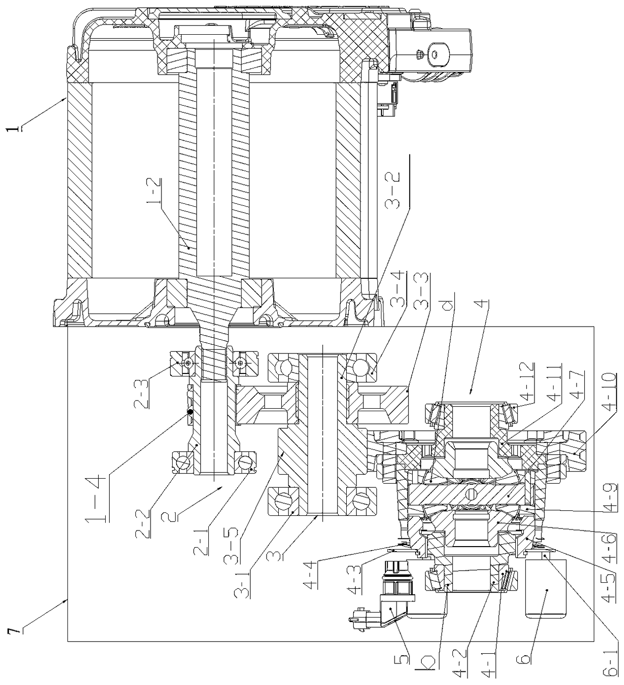
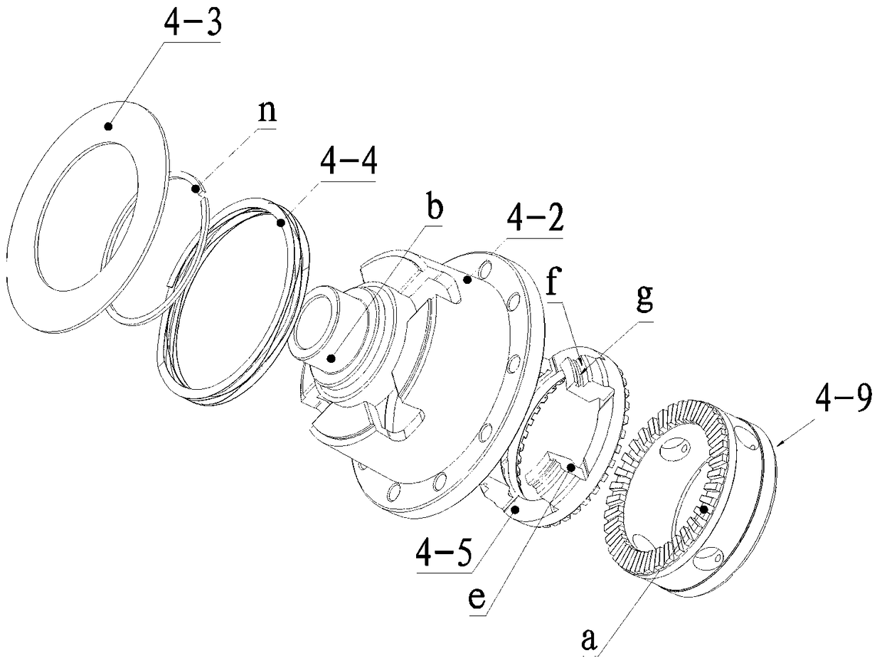
[0028] see Figure 1 to Figure 2 , an embodiment of the rear electric drive assembly of a hybrid vehicle, the rear electric drive assembly of a hybrid vehicle includes a drive motor 1 and a reducer assembly 7, and the reducer assembly 7 includes a Differential assembly 4, the differential case of the differential assembly is connected and fixed by the differential left case 4-2 and the differential right case 4-11 to form a box structure, the differential The left casing 4-2 of the transmission and the right casing 4-11 of the differential are respectively provided with an extension sleeve section b for the half shaft to pass through, and the extension sleeve section b is supported on the reducer case by a bearing. In this embodiment, the differential left housing 4-2 is in the shape of a hat, and the hat-shaped left transmission housing is used to accom...


PUM


Abstract

The invention relates to a rear electric drive assembly of a hybrid vehicle. The rear electric drive assembly of the hybrid vehicle comprises a drive motor and a reducer assembly. The reducer assemblycomprises a differential assembly mounted in a reducer case, a differential left housing and a differential right housing are provided with extended sleeve sections through allowing semi-shafts to pass, the extended sleeve sections are supported on the reducer case by bearings, a main reduction gear is fixedly connected to the differential housing, the main reduction gear receives torque output by the drive motor, a rotatable planet carrier is arranged in the differential housing in a loose fit mode, one axial end face of the planet carrier is provided with an end face tooth, an axially movable gear ring is arranged in the differential housing, an end face tooth of a gear ring is arranged on one axial end face and corresponds to the end face tooth of the planet carrier, the other axial end of the gear ring is provided with a plurality of axial mounting posts, the axial mounting posts protrude from the differential to support a signal plate, a return spring is arranged between the signal plate and the differential housing, and driving devices for driving the signal plate to perform axial displacements are arranged on the reducer.

Description

technical field [0001] The invention relates to an automobile drive axle, in particular to a rear electric drive assembly of a hybrid electric automobile. Background technique [0002] With the increasing shortage of oil supply and the increasing environmental pollution, people are paying more and more attention to new energy vehicles. Among them, the hybrid electric vehicle has the advantages of obvious fuel saving, no mileage limit, pure electric driving, good power performance, etc., and the technology is becoming more and more mature, and has become the mainstream in the market. However, due to the limited space in the front cabin of the hybrid electric vehicle, the motor Placing it in the front compartment will lead to major changes in the vehicle, increased costs, and a long development cycle; and if the motor is placed in the front compartment of the engine, the output power of the motor must pass through the transmission mechanism to reach the rear wheels, which will...

Claims


Application Information

Patent Timeline
Patent Type & Authority Applications(China)
IPC IPC(8): B60K17/12B60K17/16B60K6/365B60K6/50
CPCB60K6/365B60K6/50B60K17/12B60K17/16
Inventor 王鹤周朝东邓旺宋亚科王海兵王鑫金良宽毛江赵林燕
Owner CHONGQING TSINGSHAN IND
Why Eureka
Try Eureka