Waterproof construction method of anti-floating anchor

A technology of anti-floating anchor rods and construction methods, applied in infrastructure engineering, protection devices, buildings, etc., can solve the hidden danger of water leakage at the interface between the anchor rod and SBS waterproof membrane, the hidden danger of water leakage at the interface between the anchor rod and waterproof membrane, etc. problems, to achieve the effect of reducing the risk of water leakage, high tensile strength, and convenient construction

Inactive Publication Date: 2018-07-27
CHINA CONSTR SIXTH ENG BUREAU CIVILENG +1
View PDF9 Cites 4 Cited by
  • Summary
  • Abstract
  • Description
  • Claims
  • Application Information

AI Technical Summary

Problems solved by technology

There is a hidden danger of water leakage at the interface between the anchor rod and the SBS waterproof membrane in this patent. Although the asphalt ointment is pasted, it only plays an auxiliary role
[0005] The Chinese patent with the application number CN201621488750.9 discloses "a waterproof structure for anti-floating anchor rod joints for deep foundation pits", including a concrete floor and anti-floating anchor rods. At least three anti-floating anchor rods are arranged in the concrete floor, and The upper half of the anti-floating anchor is buried in the concrete floor, and the lower half passes through the concrete cushion. The waterproof construction structure also includes a cement-based permeable crystalline waterproof layer and a waterproof membrane layer from bottom to top, close to the anti-floating anchor The central position is provided with a groove filled with polyurethane waterproof paint, the waterproof coiled material is divided into two layers, the anti-floating anchor is provided with a water-stop steel sheet, and the anti-floating anchor is paved with thick saline-alkali-resistant modified asphalt ( SBS) additional layer of waterproof membrane; there is a hidden danger of water leakage at the interface between the anchor rod and the waterproof membrane, although asphalt ointment is attached, it only plays an auxiliary role

Method used


Image

  • Waterproof construction method of anti-floating anchor

Examples


Embodiment 1

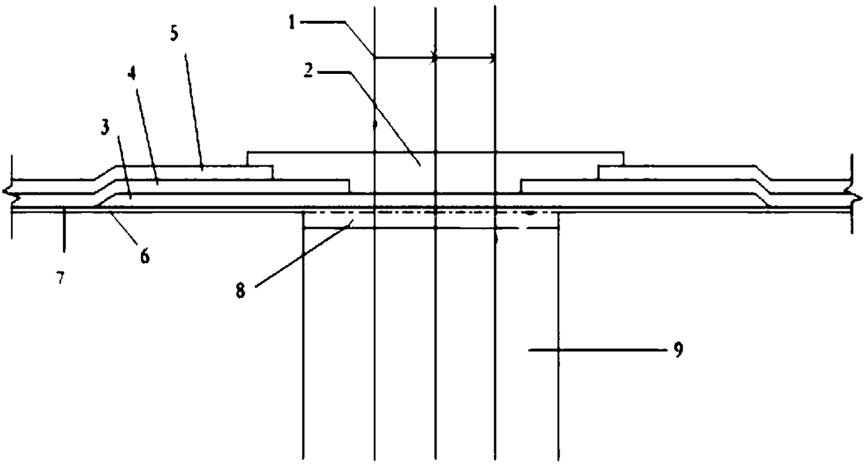
[0033] (1) Cushion 6 is poured at the bottom of the foundation pit, and on the cushion 6, holes are drilled at intervals successively with a bolt drill. After the rig drills into the design depth of 12m, a pressure grouting is started immediately, and the drill rod is lifted while Inject cement mortar until the cement mortar overflows from the bore hole 9;

[0034] (2) After the initial setting of the cement mortar of the primary pressure grouting and before the final setting, the secondary grouting pipe is lowered together with the anti-floating anchor rod 1 into the borehole of the primary pressure grouting. If it is difficult to lower the local position, use The vibrating hammer is assisted in lowering to control the exposed length of the anchor bar to 600mm;

[0035] (3) Use the secondary grouting pipe for secondary grouting;

[0036] (4) After the mortar slurry strength of the secondary grouting reaches 90% of the design strength 30MPa, carry out the pull-out bearing cap...

Embodiment 2

[0045] (1) Cushion 6 is poured at the bottom of the foundation pit, and on the cushion 6, holes are drilled at intervals successively with a bolt drill. After the rig drills into the design depth of 16m, a pressure grouting is started immediately, and the drill pipe is lifted while Inject cement mortar until the cement mortar overflows from the bore hole 9;

[0046] (2) After the initial setting of the cement mortar of the primary pressure grouting and before the final setting, the secondary grouting pipe is lowered together with the anti-floating anchor rod 1 into the borehole of the primary pressure grouting. If it is difficult to lower the local position, use The vibrating hammer is assisted in lowering to control the exposed length of the anchor bar to 800mm;

[0047] (3) Use the secondary grouting pipe for secondary grouting;

[0048] (4) After the mortar slurry strength of the secondary grouting reaches 90% of the design strength 30MPa, carry out the pull-out bearing ca...

Embodiment 3

[0057] (1) Cushion 6 is poured at the bottom of the foundation pit, and on the cushion 6, holes are drilled at intervals successively with a bolt drill. After the rig drills into the design depth of 17m, a pressure grouting is started immediately, and the drill rod is lifted while Inject cement mortar until the cement mortar overflows from the bore hole 9;

[0058] (2) After the initial setting of the cement mortar of the primary pressure grouting and before the final setting, the secondary grouting pipe is lowered together with the anti-floating anchor rod 1 into the borehole of the primary pressure grouting. If it is difficult to lower the local position, use The vibrating hammer is assisted in lowering to control the exposed length of the anchor bar to 700 mm;

[0059] (3) Use the secondary grouting pipe for secondary grouting;

[0060] (4) After the mortar slurry strength of the secondary grouting reaches 90% of the design strength 30MPa, carry out the pull-out bearing ca...


PUM

PropertyMeasurementUnit
lengthaaaaaaaaaa

Abstract

The invention discloses a waterproof construction method of an anti-floating anchor. The method comprises following steps that a cushion layer is poured on the bottom of a foundation pit, the cushionlayer is subject to interval drilling in sequence through an anchor drilling rig, after the drilling rig performs drilling to the design depth, primary pressure grouting is carried out, cement mortaris injected while a drill rod is lifted until the cement mortar flows out of a drilling hole; after the cement mortar of secondary pressure grouting is subject to initial setting and before final setting, a secondary grouting pipe descends along with the anti-floating anchor to enter a drill hole of the primary pressure grouting; secondary grouting is carried out; anti-pull bearing force test of the anti-floating anchor is carried out; if the anti-floating anchor is checked out, soil clipping layer on the root of the anti-floating anchor is chiseled and removed, cement waterproof mortar is smeared and is flushed with the cushion layer; waterproof joint treatment on the connecting position of the anti-floating anchor and the foundation is carried out. Through the method, water leaking risksare reduced, and the anti-pulling bearing force of the anti-floating anchor is high.

Description

technical field [0001] The invention relates to a waterproof construction method, in particular to a waterproof construction method for an anti-floating anchor rod. Background technique [0002] Anti-floating anchor rods, also called anti-floating piles, are a kind of anti-floating measures for underground structures in construction projects. Anti-floating anchors are different from ordinary foundation piles, and have their own unique properties. The biggest difference from ordinary foundation piles is that foundation piles are usually compression piles, and the pile body bears the building load pressure, and the force is from the top of the pile to the bottom of the pile. Transmission, the force of the pile body changes with the change of the building load; while the anti-floating pile bears the tensile force on the uplift pile body, and the force of the ordinary anti-floating pile is also transmitted from the top of the pile to the bottom of the pile, and the force on the ...

Claims


Application Information

Patent Timeline
Patent Type & Authority Applications(China)
IPC IPC(8): E02D31/02E02D31/12
CPCE02D31/02E02D31/12
Inventor 王丽梅袁银书付国刚郭建东张振禹王保华
Owner CHINA CONSTR SIXTH ENG BUREAU CIVILENG
Why Eureka
Try Eureka