
Heat pump drying system with deep supercooling

A heat pump drying and deep subcooling technology, applied in heat pump, drying, dryer and other directions, can solve the problems of high condensing temperature of heat pump unit, not considering heat pump subcooling and energy saving requirements, energy loss and other problems

Inactive Publication Date: 2018-07-27
QINGDAO UNIV +2
View PDF5 Cites 0 Cited by
  • Summary
  • Abstract
  • Description
  • Claims
  • Application Information

AI Technical Summary

Problems solved by technology

[0003] After searching, the invention patent of "a drying device and drying method" applied for application number 201310297341.5 invented a new type of drying system using a heat pump dehumidification device, which can dry a variety of melons and fruits and has good adaptability, but it has high water content in drying. The supercooling and energy-saving requirements of the heat pump are not considered during high-rate melon and fruit operation and continuous high-load operation; the invention patent of "heat pump grain dryer" applied for application number 201310321715.2 has invented a drying system with one or more heat pump units, and the drying temperature is relatively low. High, when the drying capacity is relatively large, the refrigerant may have problems of insufficient subcooling and energy loss; the invention patent of "a new type of heat pump drying device" applied for in 201310641067.9 The refrigerant circulation circuit in the heat pump drying system includes the main Condenser and auxiliary condenser, the system is not equipped with a device that promotes the complete condensation and subcooling of the refrigerant during long-term continuous operation. It is used in the heat pump system in the field of material drying, and some heat pump units have higher condensation temperatures or lower subcooling degrees. Small, which limits the improvement of unit cooling capacity and system thermal efficiency

Method used


Image

  • Heat pump drying system with deep supercooling
  • Heat pump drying system with deep supercooling

Examples


Embodiment Construction

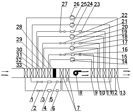
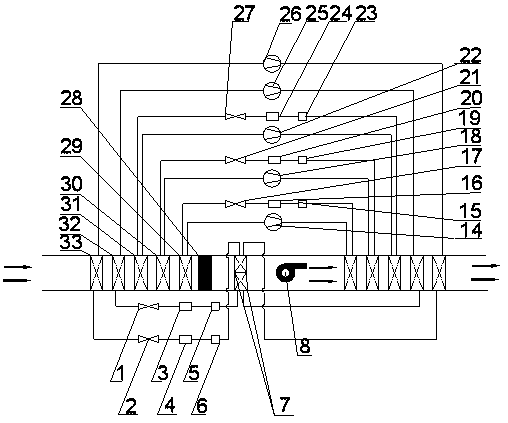
[0010] Taking the heat pump drying system with deep subcooling composed of five sets of heat pump units as a specific example, combined with figure 1 and figure 2 The present invention is described in detail so that the advantages and features of the present invention can be more easily understood by those skilled in the art, so as to define the protection scope of the present invention more clearly.

[0011] Heat pump drying system with deep subcooling, including: five sets of independent heat pump units, a subcooler group (7) composed of two subcoolers, a fan (8) and a central controller; each heat pump unit includes a compressor ( 14, 18, 22, 25, 26), condenser (9, 10, 11, 12, 13), liquid receiver (16, 20, 24, 3, 4), filter drier (15, 19, 23, 5, 6), expansion valves (17, 21, 27, 1, 2) and evaporators (29, 30, 31, 32, 33) constitute a refrigerant circulation circuit. Along the direction of air flow, multiple sets of heat pump units are defined as #1 heat pump unit, #2 hea...


PUM


Abstract

The invention relates to a heat pump drying system with deep supercooling capable of being used in the drying field of various materials. The system comprises a plurality of independent heat pump units, a subcooler unit, a fan and a central controller, wherein each of the heat pump units comprises a compressor, a condenser, a liquid storage device, a drying filter, an expansion valve and an evaporator. The heat pump unit which is relatively high in condensing temperature or relatively small in supercooling degree in the heat pump drying system with deep supercooling is provided with a subcooler, and a liquid refrigerant out of the condenser is cooled by means of dehumidified low-temperature air, so that the supercooling degree is improved greatly and the refrigerating capacity is improvedgreatly. When the plurality of subcoolers are adopted, the subcoolers can be connected in parallel or in series on the air side. In the system, drying air is successively cooled and dehumidified stageby stage by the evaporators and is then reheated by means of the condensers, so that the air is cooled and heated gradiently, and the heat pump drying system has the advantages of being small in heattransfer temperature difference, energy-saving and efficient.

Description

technical field [0001] The invention relates to the technical field of heat pump drying, in particular to a heat pump drying system with deep subcooling. Background technique [0002] In the field of drying, with the strengthening of national atmospheric environmental protection and the continuous enhancement of environmental awareness of enterprises and individuals, heat pump drying has become the first choice for industrial and agricultural drying production processes. In the traditional coal-fired or gas-fired boiler hot air drying system, the energy in the coal is transferred to the air through combustion, and the high-temperature air is blown over the items to be dried, and the items are dried by heating and moisture absorption. In this process, the thermal efficiency of the system is very low, and a large amount of nitrogen oxides, sulfides, and carbon dioxide emissions will be generated, which is not conducive to energy saving and environmental protection. A new dryin...

Claims


Application Information

Patent Timeline
IPC IPC(8): F26B23/00F25B30/02F25B49/02
CPCF26B23/00F25B30/02F25B49/02
Inventor 王德昌郭安柱李延辉
Owner QINGDAO UNIV
Learn More